Structural component and method and a mold tool for its production

a technology of structural components and molds, applied in the direction of lamination, magnetic recording, molds, etc., can solve the problem of unreflectiveness, achieve the effect of improving mechanical characteristics, reducing production costs, and reducing production costs

Inactive Publication Date: 2005-03-24
DECOMA GERMANY
View PDF4 Cites 17 Cited by
  • Summary
  • Abstract
  • Description
  • Claims
  • Application Information

AI Technical Summary

Benefits of technology

[0009] In order to obtain the effect with the structural component as explained above of uneven reflection on the exterior surface of the varnish film, the method in accordance with the invention is preferably carried out with a mold tool, i.e. a back molding die and / or a thermoforming die whereby the mold tool has a surface facing the cavity of the die in which a surface structure is ingrained. If during back molding and / or thermoforming of the varnish film its exterior surface is pressed against the surface of the mold tool, the surface structure of the mold surface is replicated on the exterior surface of the varnish film. This applies equally to the production method by means of rotational centrifuging, in which the Duromer molding material mentioned above is used. As a result therefore the varnish film, which possesses a substantially smooth exterior surface before thermoforming and / or back molding, acquires an exterior surface with a surface structure, which causes uneven reflection.
[0013] Alternatively, it is also possible with a further refinement of the invention to impart a surface structure on the exterior surface of the varnish film during both the contouring and back molding steps. In this case therefore it concerns overlaying replications of the surface structure ingrained in the various mold tools (for example thermoforming die and back molding die) on the exterior surface of the varnish film, the replications of which build up finally to an overall structure on the exterior surface of the varnish film. If a corresponding surface structure is provided both in the die for contouring and in the back molding die for replication on the exterior surface of the varnish film, advantageously more complex and finer structures can be obtained on the exterior surface of the varnish film so that the optical appearance of the varnish film resembles more closely that of a varnished metal part.
[0015] The internal die pressure, which arises in the die cavity during the foaming process, is only a few bar, and can for example reach a value of up to approximately 15 bar. Since such internal pressure is comparatively low, the surface of the varnish film is preferably structured in the previous processing step of contouring, in particular by way of thermoforming. Alternatively, in the case of a structural component which is back foamed in the last processing step, the mold tool used for molding has a corresponding surface structure on the surface facing the cavity of the die. The surface structure is therefore essentially imparted on the exterior surface of the varnish film during contouring, so that the comparatively low internal pressures do not disadvantageously affect the desired structure during the back foaming process.
[0016] A further effect of low internal die pressure during the foaming process described is that possible minute errors in the preferably thermoformed film can no longer be “ironed-out” during back foaming. To guarantee an excellent surface (the so-called “class A surface finish”) of the varnish film and / or the structural component—apart from the quality of the raw materials used—the surface quality and cleanliness of the thermoforming die is of crucial importance.
[0017] In accordance with another alternative refinement of the invention the back molding of the varnish film is carried out in particular by back injection molding with a thermoplastic sheet. In the case of back injection molding onto the varnish film the internal pressure in the cavity assumes a higher value in comparison to back foaming. Thus, the internal pressure can reach a value of approximately 700 bar for example. Accordingly, in this case the surface structure is preferably ingrained in the surface of the injection molding die, since due to the very high internal pressure in the cavity the varnish film is pressed against the die surface. This leads to reliable replication of the surface structure, which is ingrained in the die surface, on the exterior surface of the varnish film. In addition, as a result of the structure ingrained in the back molding die, the disadvantage that an otherwise smooth surface of the back injection molding die could in an undesirable way smooth out the structure of the exterior surface of the varnish film produced previously during the thermoforming process is avoided.
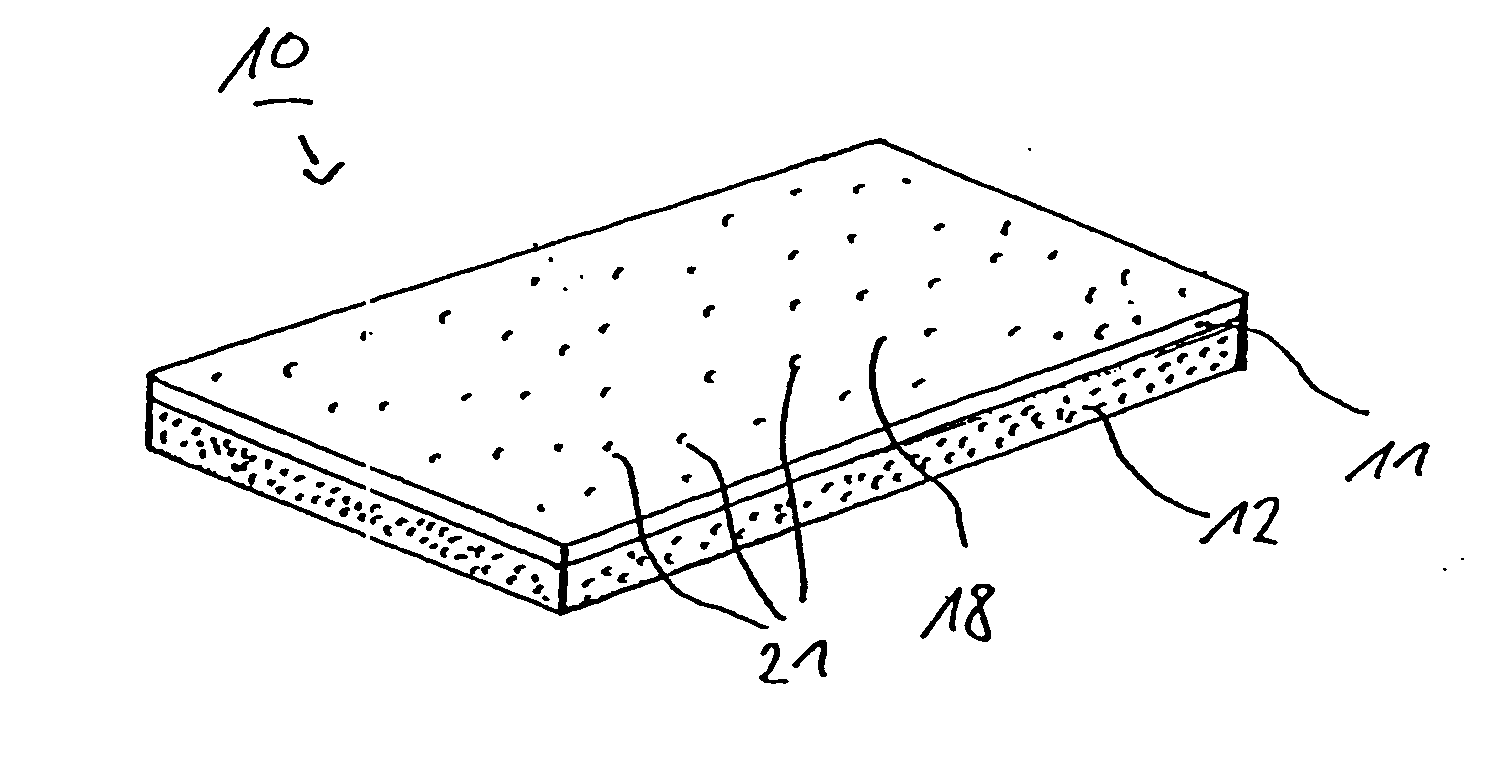
[0029] If the structural component in accordance with the invention, as explained above, is used for example in automotive construction, a preferred specific application of such a component relates to use as mudguards, engine bonnet, tailgates, a side part or even as a roof module. The mechanical characteristics of the structural component in accordance with the invention can be excellently influenced by an admixture of glass fibers, in the form of short or long glass fibers. Trials have shown that passenger compartments with roof modules consisting of the structural components in accordance with the invention have greater rigidity than conventional passenger compartments, which are exclusively produced from sheet metal.

Problems solved by technology

As a result therefore the varnish film, which possesses a substantially smooth exterior surface before thermoforming and / or back molding, acquires an exterior surface with a surface structure, which causes uneven reflection.

Method used


Image

  • Structural component and method and a mold tool for its production
  • Structural component and method and a mold tool for its production

Examples


Embodiment Construction

[0034] A structural component 10 in accordance with the invention is illustrated in FIG. 1 in a perspective view. The structural component 10 includes a varnish film 11, underside surface of which is back foamed with a carrier material 12, preferably with a PUR system. The carrier material 12 is well adhered to the varnish film 11 due to fusion of the varnish film 11 with the carrier material 12 on the boundary layer between these two materials and altogether imparts the wanted mechanical characteristics on the structural component 10.

[0035] Before the varnish film 11 is back foamed with the carrier material 12, it is thermoformed in a thermoforming die 15 (FIG. 2), in order to approximately acquire the definitive contour of the structural component to be produced. FIG. 2 shows a lower half of the thermoforming die 15. For carrying out thermoforming, the varnish film 11 is laid in the lower half of the thermoforming die 15. Subsequently, an upper half of the thermoforming die, whic...


PUM

PropertyMeasurementUnit
pressureaaaaaaaaaa
internal pressureaaaaaaaaaa
temperaturesaaaaaaaaaa

Abstract

A method is described for manufacturing a structural component (10) with a varnish exterior surface, with the steps of: providing of a varnish film (11), the exterior surface (18) of which is substantially smooth, thermoforming the varnish film and back molding the varnish film with a carrier material (12) in particular made of plastic, wherein during at least one of the two steps consisting of thermoforming and back molding, an exterior surface (18) of the varnish film is provided with a surface structure (21), which causes uneven reflection on the exterior surface.

Description

FIELD OF THE INVENTION [0001] The invention relates to a structural component with a varnished exterior surface, which is provided with a surface structure and also a method and a mold tool for its production. BACKGROUND OF THE INVENTION [0002] Structural components are of importance in the most diverse technical applications, when outside forces affect such components or if a complete assembly, which has to meet high rigidity and strength requirements, is formed by such components. In particular with regard to automotive construction, the use of structural components is known in the form of roof members, door linings, mudguards and the like. Generally, in the case of an automobile body, such structural components are produced from metal, which is then varnished, wherein the paint prevents undesirable corrosion of the metal and imparts a desired optical appearance on the body. Varnished structural components made of metal are generally not completely smooth on their exterior surface...

Claims


Application Information

Patent Timeline
Patent Type & Authority Applications(United States)
IPC IPC(8): B29C44/14B29C45/14B29C51/16B32B27/06
CPCB29C45/1418B29C45/14778Y10T428/24355B32B37/00B32B27/06B32B37/153B32B2307/416B32B5/18B32B27/065B32B2266/0278B32B38/06
Inventor FLAIG, JOACHIMLACHENMAIER, AXEL
Owner DECOMA GERMANY
Why Eureka
Try Eureka