
Multi-wave length laser source

a laser source and multi-wavelength technology, applied in the field of lasers, can solve the problems of reducing the emission properties of fiber lasers, affecting the performance of short single-mode fiber lasers, and avoiding laser resonators

Inactive Publication Date: 2005-03-24
UNIV LAVAL
View PDF12 Cites 47 Cited by
  • Summary
  • Abstract
  • Description
  • Claims
  • Application Information

AI Technical Summary

Benefits of technology

In accordance with another aspect, the invention provides a device suitable for providing materia...

Problems solved by technology

Fiber lasers are usually not considered to be good candidates for multi-frequency laser sources because the gain competition between the lasing frequencies results in an unstable output that allows emission over only a few closely spaced wavelengths.
Unfortunately, high levels of germania dopants leads to clustering of the rare earth ions and reduces the emission properties of fiber lasers.
This loss is very detrimental to the performance of short single-mode fiber lasers.
Emission over a larger number of wavelengths can be achieved by cooling the fiber to a cryogenic temperature, a rather unpractical approach.
By immersing the laser in liquid nitrogen multi-frequency emission is obtained over 17 wavelengths as depicted in FIG. 4b. However, as the temperature is increased, gaps appear in the optical spectrum and the power becomes unstable as depicted in FIGS. 4c and 4d.
Hübner et al. have thus realized a five-wavelengths laser source having an output spectrum of the type shown in FIG. 5b. Each fiber laser being 5 cm long, the resulting structure is therefore quite long and difficult to stabilize.
Although the available output power obtained from each laser is high, approximately 3 mW, the number of pump laser diodes increases the cost and complexity. FIG. 6b shows the output spectrum (optical power in dBm vs wavelength in nm) of the configuration of FIG. 6a.
This approach is however limited in terms of the number of wavelengths that could be achieved since all the laser cavities are located at the same position on the optical fiber.

Method used


Image

  • Multi-wave length laser source
  • Multi-wave length laser source
  • Multi-wave length laser source

Examples


Embodiment Construction

Before explaining the disclosed embodiment of the present invention in detail it is to be understood that the invention is not limited in its application to the details of the particular arrangement shown since the invention is capable of other embodiments. Also, the terminology used herein is for the purpose of description and not of limitation.

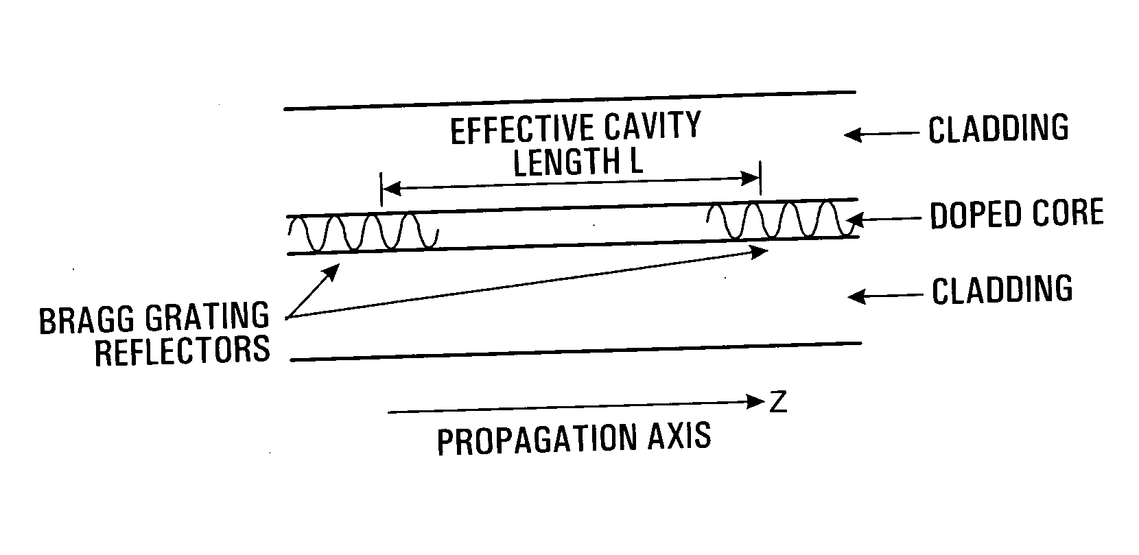
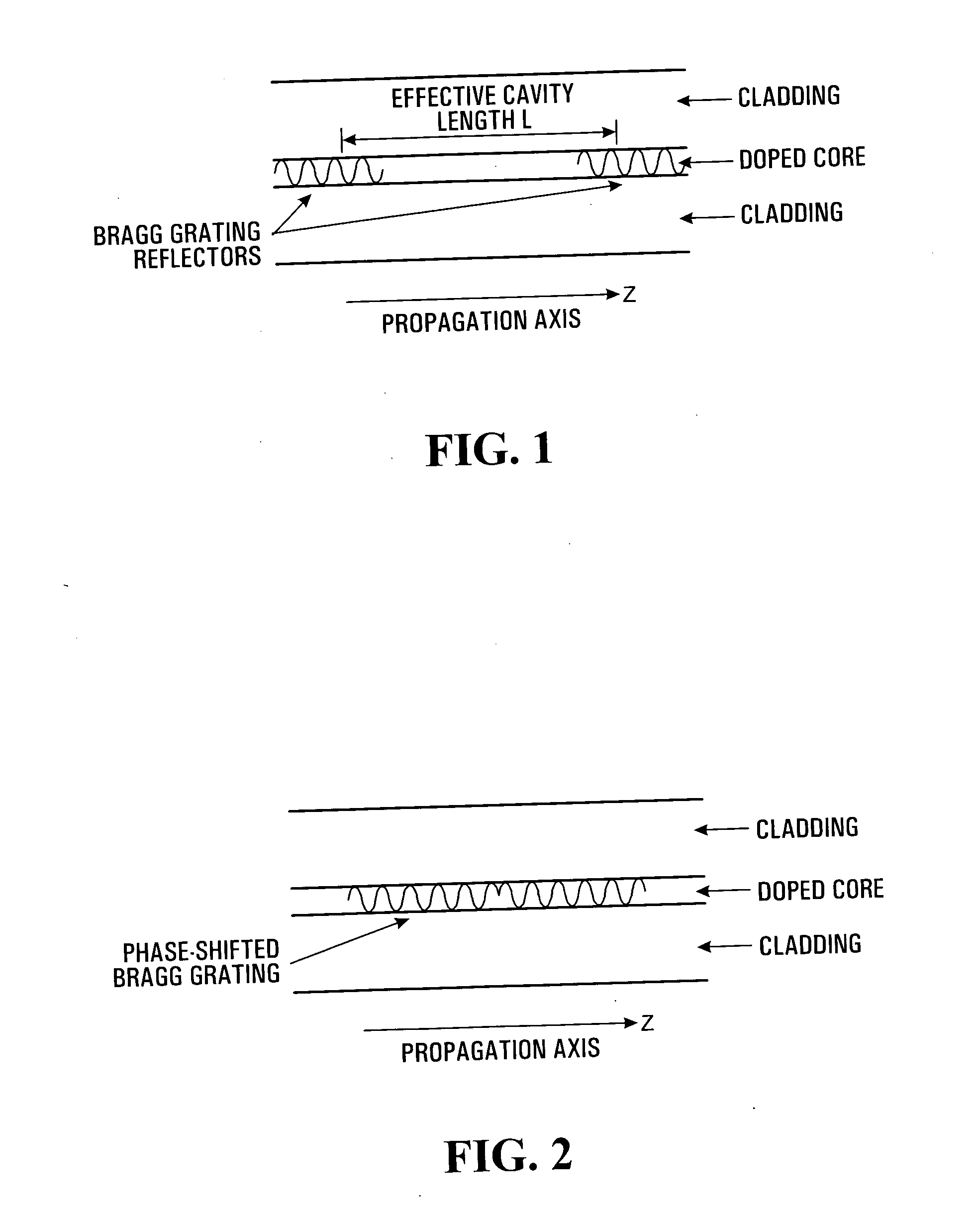
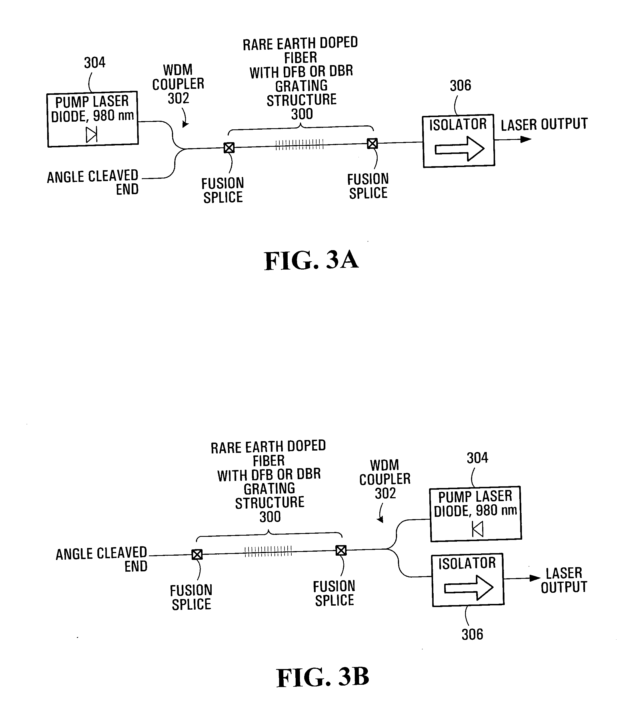
With reference to FIG. 8a, there is shown a simplified diagram of a multi-wavelength laser source 801 in accordance with a specific example of implementation of the invention. As shown, the multi-wavelength laser source 801 includes a laser source unit 800, a gain section 802 and an output 806. The laser source unit 800 is adapted for generating an energy signal and applying this energy signal to the gain section 802. The gain section 802 includes a gain medium having a superstructure grating 804. The superstructure grating 804 forms a distributed Fabry-Perot-like structure. The superstructure grating causes a multi-wavelength laser signa...


PUM


Abstract

A multi-wavelength laser source is provided including a pump laser unit, a gain section and an output. The pump laser unit generates an energy signal, which is applied to the gain section. The gain section includes a gain medium with having a superstructure grating forming a distributed Fabry-Perot-like structure. The superstructure grating causes a multi-wavelength laser signal to be generated when the energy signal is applied to the gain medium. The multi-wavelength laser signal is then released at the output.

Description

FIELD OF THE INVENTION The present invention relates generally to lasers and, more particularly, to a multi-wavelength laser source. This invention is particularly application in the fields of telecommunications, optics, sensing and spectroscopy. BACKGROUND OF THE INVENTION Compared to other compact laser sources, fiber lasers present superior performance in terms of spectral purity and noise. Furthermore, their output is readily compatible with fiber optics systems and components by fusion splicing and standard connectors. Nowadays fiber lasers with high spectral purity are typically realized using photo-induced fiber Bragg gratings. In recent years, optical fiber lasers have been developed to cover a wide range of spectral bands. The gain medium of these lasers is typically composed of silica, fluoride or chalcogenide host matrix doped with rare earth ions. Of particular interest is erbium-doped silica which produces gain in the 1530 to 1610 nm wavelength band. This spectral re...

Claims


Application Information

Patent Timeline
IPC IPC(8): H01S3/067H01S3/08H01S3/094H01S3/0941
CPCH01S3/0675H01S3/0941H01S3/094046H01S3/08086
Inventor DOUCET, SERGELAROCHELLE, SOPHIESLAVIK, RADANCASTONGUAY, ISABELLE
Owner UNIV LAVAL
Learn More