
Predicting motion vectors for fields of forward-predicted interlaced video frames

a technology of motion vectors and video frames, applied in the field of predicting motion vectors for forward-predicted interlaced video frames, can solve the problems of large amount of digital video storage and transmission capacity, lossless compression, and many computers and computer networks lack the resources to process raw digital video, so as to improve the accuracy of motion vector prediction and reduce the bitrate associated

Active Publication Date: 2005-03-10
MICROSOFT TECH LICENSING LLC
View PDF99 Cites 164 Cited by
  • Summary
  • Abstract
  • Description
  • Claims
  • Application Information

AI Technical Summary

Benefits of technology

In summary, the detailed description is directed to various techniques and tools for encoding and decoding predicted video images in interlaced video. Described techniques include those for computing motion vector predictors for block or macroblocks of fields of interlaced video frames. These techniques improve the accuracy of motion vector prediction in many cases, thereby reducing the bitrate associated with encoding motion vector information for fields of interlaced video frames. The various techniques and tools can be used in combination or independently.

Problems solved by technology

Digital video consumes large amounts of storage and transmission capacity.
Many computers and computer networks lack the resources to process raw digital video.
Compression can be lossless, in which quality of the video does not suffer but decreases in bit rate are limited by the complexity of the video.
Or, compression can be lossy, in which quality of the video suffers but decreases in bit rate are more dramatic.
Such motion vector prediction fails to adequately predict motion vectors for macroblocks of fields of interlaced video frames in many cases.
Whatever the benefits of previous video compression and decompression techniques, however, they do not have the advantages of the following techniques and tools.

Method used


Image

  • Predicting motion vectors for fields of forward-predicted interlaced video frames
  • Predicting motion vectors for fields of forward-predicted interlaced video frames
  • Predicting motion vectors for fields of forward-predicted interlaced video frames

Examples


Embodiment Construction

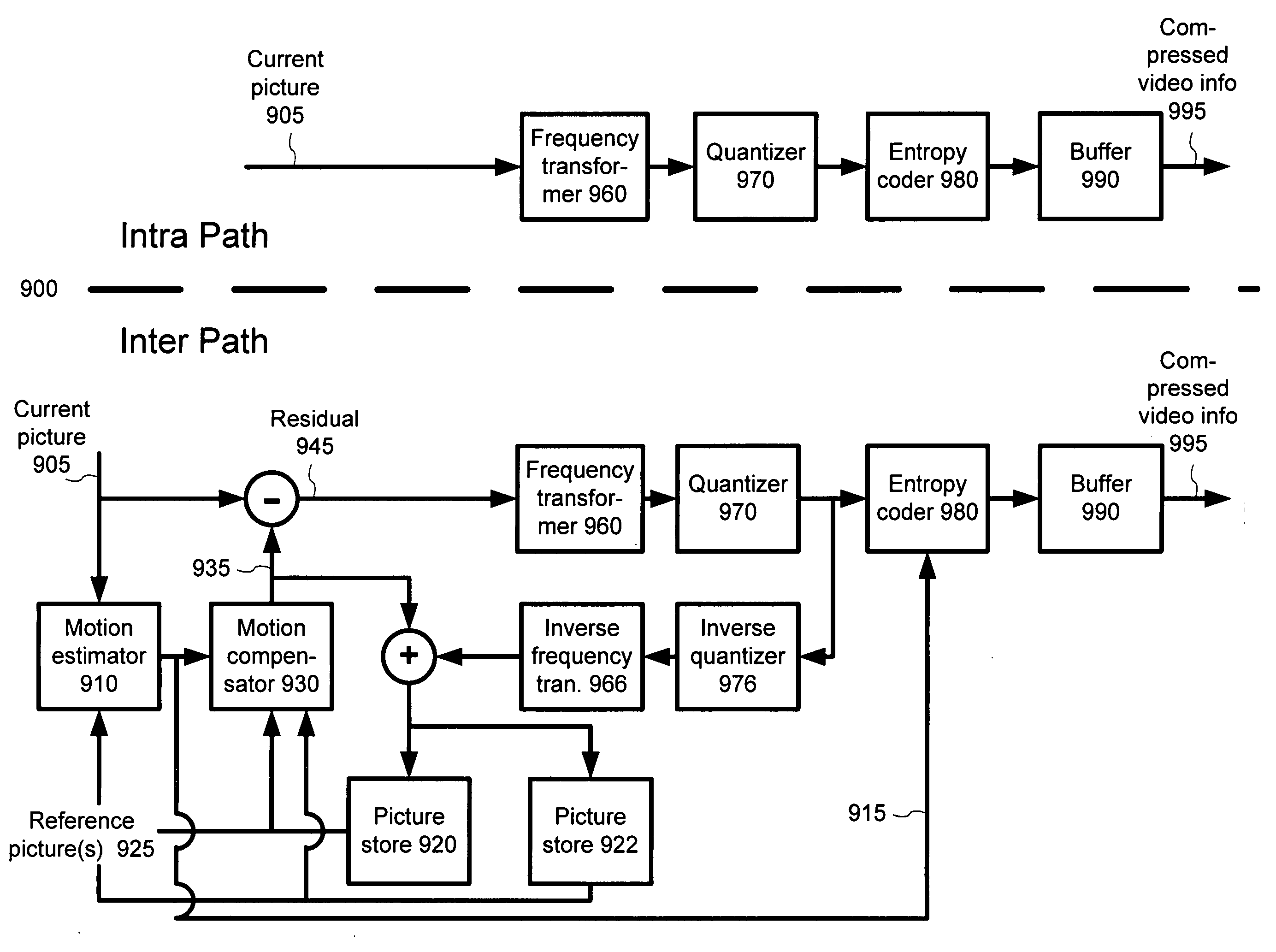
The present application relates to techniques and tools for efficient compression and decompression of interlaced video. In various described embodiments, for example, a video encoder and decoder incorporate techniques for predicting motion vectors in encoding and decoding predicted fields in interlaced video frames, as well as signaling techniques for use with a bit stream format or syntax comprising different layers or levels (e.g., sequence level, picture / image level, field level, macroblock level, and / or block level). The techniques and tools can be used, for example, in digital video broadcasting systems (e.g., cable, satellite, DSL, etc.).

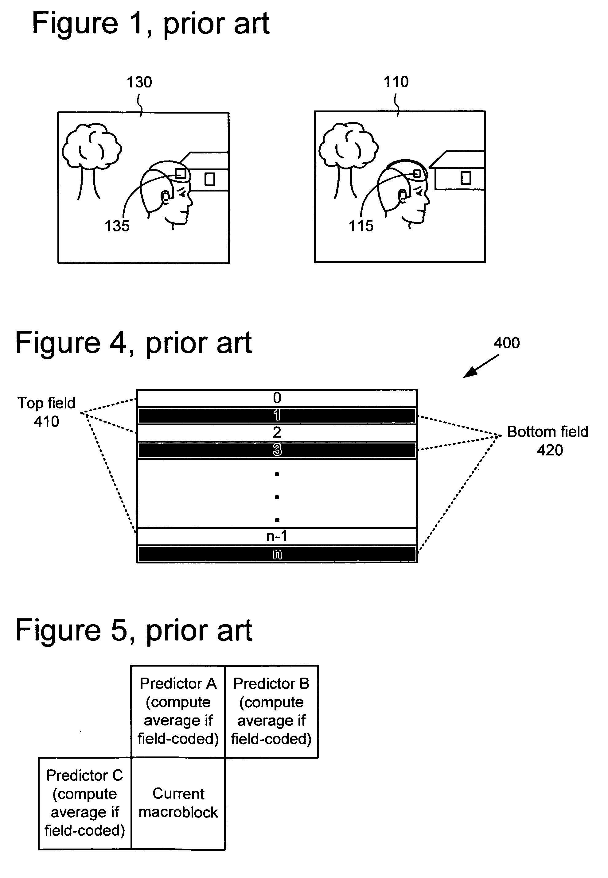
In particular, described techniques and tools improve the quality of motion vector predictors for blocks and / or macroblocks of forward-predicted fields of interlaced video frames, which in turn allows motion vectors to be more efficiently encoded. For example, techniques are described for generating predictor motion vectors for the blocks ...


PUM


Abstract

Techniques and tools for encoding and decoding predicted images in interlaced video are described. For example, a video encoder or decoder computes a motion vector predictor for a motion vector for a portion (e.g., a block or macroblock) of an interlaced P-field, including selecting between using a same polarity or opposite polarity motion vector predictor for the portion. The encoder / decoder processes the motion vector based at least in part on the motion vector predictor computed for the motion vector. The processing can comprise computing a motion vector differential between the motion vector and the motion vector predictor during encoding and reconstructing the motion vector from a motion vector differential and the motion vector predictor during decoding. The selecting can be based at least in part on a count of opposite polarity motion vectors for a neighborhood around the portion and / or a count of same polarity motion vectors.

Description

TECHNICAL FIELD Techniques and tools for interlaced video coding and decoding are described. For example, a video encoder / decoder calculates motion vector predictors for fields in interlaced video frames. BACKGROUND Digital video consumes large amounts of storage and transmission capacity. A typical raw digital video sequence includes 15 or 30 pictures per second. Each picture can include tens or hundreds of thousands of pixels (also called pels). Each pixel represents a tiny element of the picture. In raw form, a computer commonly represents a pixel with 24 bits or more. Thus, the number of bits per second, or bit rate, of a typical raw digital video sequence can be 5 million bits / second or more. Many computers and computer networks lack the resources to process raw digital video. For this reason, engineers use compression (also called coding or encoding) to reduce the bit rate of digital video. Compression can be lossless, in which quality of the video does not suffer but decre...

Claims


Application Information

Patent Timeline
IPC IPC(8): H04N19/112G06K9/36H03M7/36H03M7/40H03M7/46H04NH04N7/01H04N7/12H04N11/02H04N11/04H04N19/51
CPCH04N19/52H04N19/70H04N19/46H04N19/51H04N19/16H04N19/61H04N19/112H04N19/137H04N19/186H04N19/196H04N19/102H04N19/109H04N19/11H04N19/117H04N19/129H04N19/13H04N19/146H04N19/147H04N19/159H04N19/172H04N19/176H04N19/18H04N19/184H04N19/463H04N19/523H04N19/593H04N19/63H04N19/82H04N19/86H04N19/93
Inventor HOLCOMB, THOMAS W.
Owner MICROSOFT TECH LICENSING LLC
Learn More