
D-class signal amplification circuit

Inactive Publication Date: 2005-03-10
LAPIS SEMICON CO LTD
View PDF5 Cites 15 Cited by
  • Summary
  • Abstract
  • Description
  • Claims
  • Application Information

AI Technical Summary

Benefits of technology

[0009] The present invention has been made in view of the above problems, and an object of the invention is to provide a D-class signal amplification circuit that represses the influence by the fluctuations of the power supply voltage with a simplified construction and inexpensive components.
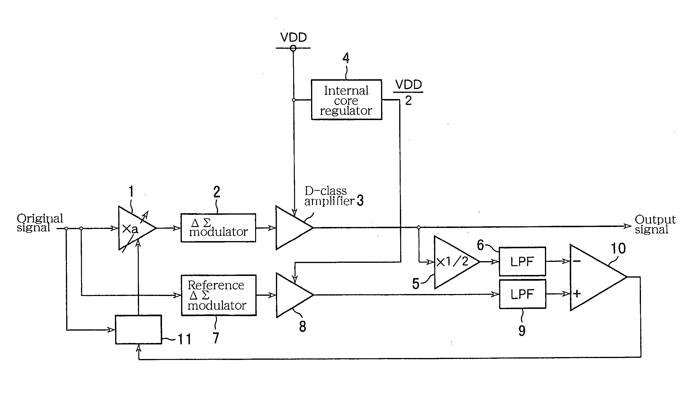
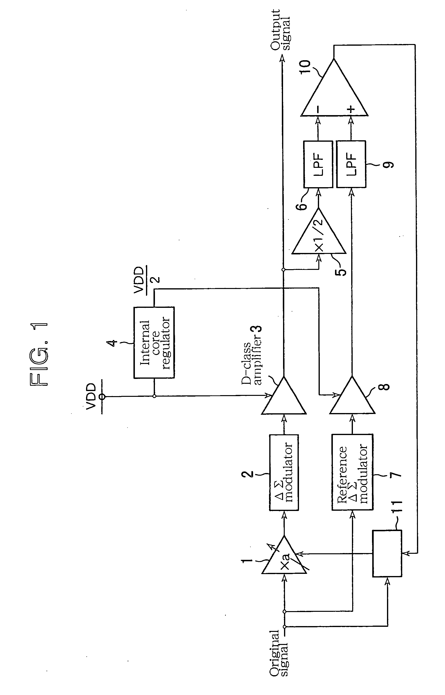
[0013] Concretely, when the first power supply voltage decreases, since the level of the signal in which the output signal from the D-class amplifier is converted into the level of the second power supply voltage becomes lower than the level of the reference signal, the correction coefficient is increased; in reverse, when the first power supply voltage increases, the correction coefficient is decreased. That is, the comparison result of the following two signals is fed back: the signal based on the output signal from the D-class amplifier, being affected by the fluctuations of the first power supply voltage, and the reference signal substantially immune to the fluctuations of the first power supply voltage; and the correction coefficient multiplied to the input signal is increased or decreased by the predetermined modifying breadth, thus repressing the influence by the fluctuations of the first power supply voltage supplied to the D-class amplifier, with the above simple control and simplified construction.
[0014] The D-class signal amplification circuit according to the invention is able to repress the influence by the fluctuations of the power supply voltage with a simple control and a simplified construction such that the comparison result of the output signal and the reference signal is fed back, and the correction coefficient multiplied to the input signal is increased or decreased by the predetermined modifying breadth.

Problems solved by technology

However, the D-class amplifier composed of a CMOS inverter transfers the power supply voltage to an output side directly, accordingly the amplifier cannot eliminate the fluctuations of the power supply voltage at all.
To achieve such a power supply voltage requires a large capacitor and inductor, which is a hindrance to reduce the circuit area and the production cost.
The amplifier requires an analog / digital converter (ADC) and so forth to generate the digital correction signal from the analog signal, which complicates the circuit construction and involves an apprehension of the cost increase.

Method used


Image

  • D-class signal amplification circuit
  • D-class signal amplification circuit
  • D-class signal amplification circuit

Examples


first embodiment

(1) First Embodiment

[0028] [Construction]

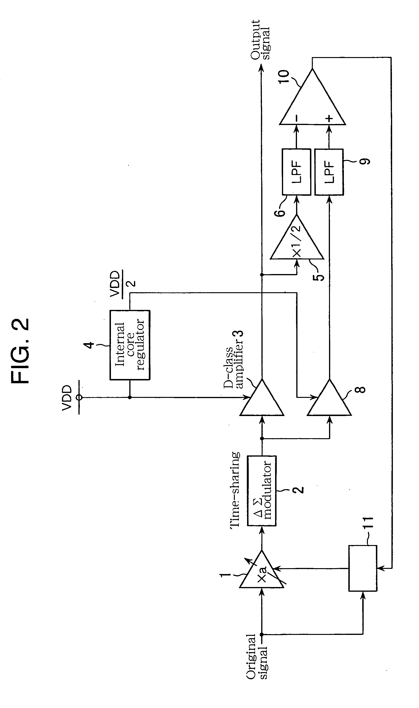
[0029]FIG. 1 illustrates a D-class signal amplification circuit relating to the first embodiment of the invention. This D-class signal amplification circuit is provided with a function that corrects the fluctuations of the power supply voltage through a feedback loop. Here, the D-class signal amplification circuit will be described with an example, which is used in the output stage of an audio signal-reproducing unit, and drives a sound-reproducing unit such as a speaker.

[0030] In FIG. 1, an original signal as an input signal inputted to an input node is a multi-bit digital audio signal (for example 16 bits). A multiplier 1 multiplies the original signal by a correction coefficient a to thereby adjust a gain thereof. A delta-sigma modulator 2 as the first delta-sigma modulation circuit executes a delta-sigma modulation to the signal that the multiplier 1 has multiplied the original signal being a 16-bit digital signal by the correction coeff...

second embodiment

(2) Second Embodiment

[0044]FIG. 4 illustrates a D-class signal amplification circuit relating to the second embodiment of the invention. The difference from the first embodiment is an addition of a correction timing adjustment circuit 12.

[0045] The correction timing adjustment circuit 12 includes a one-sample delay line 13, an exclusive NOR 14, and a counter 15. The one-sample delay line 13 retains an output before one sample (a previous output) from the comparator 10. The one-sample delay line 13 can be configured with, for example, a D-flip-flop that updates the output at the timing of the clock input falling. The exclusive NOR 14 compares the previous output from the comparator 10, inputted through the one-sample delay line 13, with the current output from the comparator 10; based on the comparison result, if both are equal, exclusive NOR 14 outputs High, and if both are different, it outputs Low. If the input from the exclusive NOR 14 is High, the counter 15 counts up, and when...

third embodiment

(3) Third Embodiment

[0047]FIG. 5 illustrates a D-class signal amplification circuit relating to the third embodiment of the invention. The D-class signal amplification circuit relating to this embodiment includes a correction timing adjustment circuit 16 in replacement for the correction timing adjustment circuit 12 relating to the second embodiment. In the second embodiment, the counter counts the frequency in which the outputs from the comparator 10 are equal in succession, and outputs the adjustment-enabling signal High only when the outputs are equal in the succession of the first predetermined frequency n1. However in this embodiment, the counter counts the frequency in which the continuing outputs from the comparator 10 are each different, and outputs an adjustment inhibiting signal High, when the outputs are each different in the succession of a second predetermined frequency n2.

[0048] The correction timing adjustment circuit 16 includes a one-sample delay line 13, an exclus...


PUM


Abstract

A D-class signal amplification circuit of the invention intends to repress the influence by a fluctuations of the power supply voltage with a simplified circuit construction and inexpensive components. The D-class signal amplification circuit includes: a multiplier that multiplies an input signal by a correction coefficient, a first modulator that executes a delta-sigma modulation to an output signal from the multiplier, a D-class amplifier supplied with a power supply voltage VDD, which amplifies an output signal from the first modulator, a voltage conversion circuit that generates a power supply voltage VDD / 2 from the power supply voltage VDD, a first low pass filter that inputs a signal converted into a level of VDD / 2 on the basis of the output signal outputted from the D-class amplifier, a reference signal generation circuit supplied with VDD / 2, which generates a reference signal on the basis of the input signal, a second low pass filter that inputs the reference signal, a first comparator that compares levels of the signals outputted from the first with the second low pass filters, and a coefficient control circuit that increases or decreases the correction coefficient by a predetermined modifying breadth, on the basis of the comparison result.

Description

BACKGROUND OF THE INVENTION [0001] 1. Field of the Invention [0002] The present invention relates to a D-class signal amplification circuit that amplifies a power of an input signal of an audio regenerative signal and so forth. [0003] This application is counterpart of Japanese patent application, Serial Number 317831 / 2003, filed Sep. 10, 2003, the subject matter of which is incorporated herein by reference. [0004] 2. Description of the Related Art [0005] A conventional audio signal-reproducing unit includes a delta-sigma modulator as a D / A conversion circuit and a D-class amplifier composed of a CMOS inverter. This type of audio signal-reproducing unit converts the input signal (original signal) being a multi-bit digital signal into one-bit analog signal by means of the delta-sigma modulator, and amplifies this analog signal by means of the D-class amplifier to drive a speaker, etc. [0006] Since an AB-class power amplifier uses an operational amplifier, the amplifier is able to eli...

Claims


Application Information

Patent Timeline
IPC IPC(8): H03F3/217H03F1/34
CPCH03F3/217H03F2200/331H03F2200/453
Inventor NAGASUE, MAKOTO
Owner LAPIS SEMICON CO LTD
Learn More