
Encapsulant layer for photovoltaic module, photovoltaic module and method for manufacturing regenerated photovoltaic cell and regenerated transparent front face substrate

a photovoltaic module and photovoltaic cell technology, applied in the field of photovoltaic module encapsulation layer, can solve the problems of further significant cost reduction, increased production, and difficulty in recovering a transparent front face substrate and a photovoltaic cell from a used module, and achieves the effect of easy recovery and easy separation

Active Publication Date: 2005-03-10
DAI NIPPON PRINTING CO LTD
View PDF22 Cites 54 Cited by
  • Summary
  • Abstract
  • Description
  • Claims
  • Application Information

AI Technical Summary

Benefits of technology

The main object of the present invention is to provide an encapsulant layer for photovoltaic module used in a photovoltaic module enabling recovering and recycling or reusing of reutilizeable resources such as a transparent front face substrate and photovoltaic cell ard the like among constituents of a photovoltaic module, and to provide a method for manufacturing a regenerated photovoltaic cell and a regenerated transparent front face substrate, of which reutilize is particularly desired because of high cost, among reutilizeable resources of a photovoltaic module.
In the encapsulant layer for photovoltaic module of the present invention, each constituent can be easily separated by heating the photovoltaic module, using this encapsulant layer, at temperatures not lower than the softening temperature of a thermoplastic resin which is a main component of the separable layer. Therefore, there is a merit that reutilizeable resources such as a photovoltaic cell and transparent front face substrate and the like can be easily recovered from a used photovoltaic module. The recovered resources can be reused as they are as constituents of a photovoltaic module, or can be recycled by heat-melting to give other materials to be used. Particularly, it is useful in that a regenerated photovoltaic cell and a regenerated transparent front face substrate can be easily obtained from a used photovoltaic module.

Problems solved by technology

Recently, since environmental problems are more and more concerned, a solar photovoltaic generation system as an inexhaustible and clean energy source attracts attention, and its amount of production is increasing year by year.
However, for an active use of a solar photovoltaic generation system in a large scale, further significant cost down is essential.
Under insistence of necessity of resource circulating type society construction, it is not desirable for the solar photovoltaic generation systems expected to support the future clean energy sources to inherit current industrial waste treating methods and to consume resources in large amount.
However, in many photovoltaic modules currently marketed, an EVA (ethylene-vinyl acetate copolymer resin) sheet is used as an encapsulant sheet, and since a thermo-setting EVA sheet is very difficult to be separated from other module constituents, it is difficult to recover a transparent front face substrate and a photovoltaic cell from a used module.
In addition, a heat cross-linking process for a long period of time is necessary, increasing energy amount in manufacturing a module.
Further, there is a problem that an acidic gas is generated as an out gas in cross-linking which deteriorates circumferential environments, and additionally, a photovoltaic cell and electrode and the like are damaged and deteriorated.

Method used


Image

  • Encapsulant layer for photovoltaic module, photovoltaic module and method for manufacturing regenerated photovoltaic cell and regenerated transparent front face substrate
  • Encapsulant layer for photovoltaic module, photovoltaic module and method for manufacturing regenerated photovoltaic cell and regenerated transparent front face substrate
  • Encapsulant layer for photovoltaic module, photovoltaic module and method for manufacturing regenerated photovoltaic cell and regenerated transparent front face substrate

Examples


example 1

(1) Production of Encapsulant Layer

100 parts by weight of a straight chain low density polyethylene having a Vicat softening temperature, measured based on JIS standard K7206 (hereinafter, referred to as Vicat softening temperature), of 80° C., a melting temperature of 90° C., a melt mass flow rate (hereinafter, referred to as MFR) of 2 g / 10 min at 190° C. and a density of 0.898 g / cm3, 2.0 parts by weight of vinyltrimethoxysilane and 0.1 part by weight of a free radical generator (t-butyl-peroxy isobutyrate) were mixed and graft-polymerized at a melt stirring temperature of 200° C. to cause silane modification, manufacturing a silane-modified straight chain low density polyethylene.

3.75 parts by weight of a hindered amine-based photo-stabilizer, 3.75 parts by weight of a benzotriazole-based ultraviolet absorber and 0.5 parts by weight of a phosphorus-based thermal-stabilizer were mixed based in 100 parts by weight of the straight chain low density polyethylene and they were mel...

example 2

The same silane-modified straight chain low density polyethylene as in Example 1 was manufactured, and the same master batch as in Example 1 was manufactured.

100 parts by weight of the above mentioned silane-modified straight chain low density polyethylene and 5 parts by weight of the above mentioned waster batch were mixed, and a film of 400 μm was formed in the same manner as in Example 1.

Film formation could be conducted without problems. The appearance and total ray transmittance of the resulting film were excellent. The polymerized Si amount in the resulting film was 3000 ppm.

A photovoltaic module was manufactured in the same manner as in Example 1. The encapsulant layer was cut out from the resulting photovoltaic module, and its gel fraction was measured to be 0%.

example 3

The same silane-modified straight chain low density polyethylene as in Example 1 was manufactured, and the same master batch as in Example 1 was manufactured.

1. Separable Layer (Outer Layer)

To 20 parts by weight of the above mentioned silane-modified straight chain low density polyethylene, 80 parts by weight of a straight chain low density polyethylene having a Vicat softening temperature of 70° C., a melting temperature of 90° C., a MFR of 3.5 g / 10 min at 190° C. and a density of 0.900 g / cm3 and 5 parts by weight of the above mentioned master batch were added and mixed.

2. Filling Layer (Inner Layer)

A straight chain low density polyethylene, having a Vicat softening temperature of 75° C., a melting temperature of 100° C., a MFR of 3.5 g / 10 min at 190° C. and a density of 0.902 g / cm3, was used.

The above mentioned separable layer and filling layer were laminated in the order of separable layer, filling layer and separable layer. The film thickness ratio was 1:6:1. In manuf...


PUM

PropertyMeasurementUnit
melt mass flow rateaaaaaaaaaa
Vicat softening temperatureaaaaaaaaaa
total ray transmittanceaaaaaaaaaa

Abstract

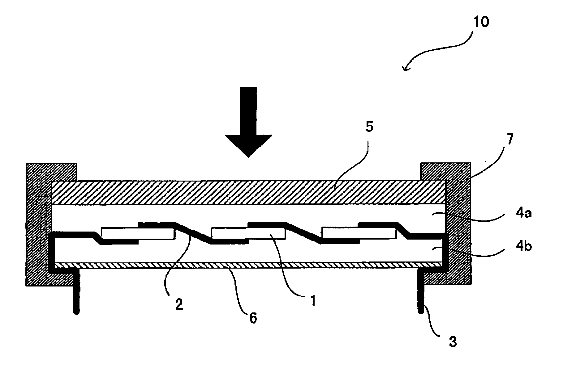
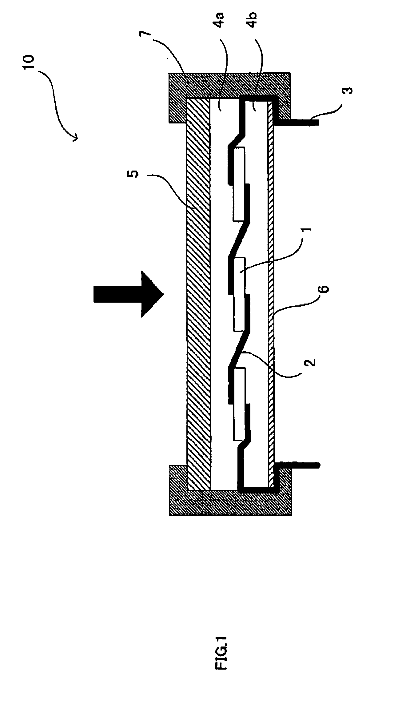
The main object of the present invention is to provide an encapsulant layer for photovoltaic module used in a photovoltaic module enabling recovering and recycling or reusing of reutilizeable resources such as a transparent front face substrate and photovoltaic cell and the like among constituents of a photovoltaic module, and to provide a method for manufacturing a regenerated photovoltaic cell and a regenerated transparent front face substrate. The present invention attains the above mentioned object by providing an encapsulant layer for photovoltaic module, wherein the encapsulant layer for photovoltaic module is used in a photovoltaic module formed by laminating: a transparent front face substrate; a photovoltaic cell carrying a wiring electrode and a takeoff electrode, and an encapsulant layer is placed on at least one surface; and a rear face protecting sheet, in this order, comprising a separable layer formed mainly of a thermoplastic resin (a) having a peeling strength from the transparent front face substrate, measured in a 180° peeling test under a 25° C. atmosphere, in a range of 1 N / 15 mm width to 150 N / 15 mm width, (b) having a Vicat softening temperature, measured based on JIS standard K7206, in a range of 60° C. to 128° C., and (c) having a melt mass flow rate, measured based on JIS standard K7210, in a range of 0.1 g / 10 min to 50 g / 10 min, and wherein (d) an output maintenance factor of photoelectronic power, before and after a test measured based on a standard, of the photovoltaic module using the encapsulant layer is in a range of 80% to 100%.

Description

BACKGROUND OF THE INVENTION 1. Field of the Invention The present invention relates to an encapsulant layer for photovoltaic module comprising a transparent front face substrate, photovoltaic cell and a separable layer, to a method for manufacturing a regenerated photovoltaic cell and a regenerated transparent front face substrate and to a method for reutilizing a photovoltaic module. 2. Description of Related Art Recently, since environmental problems are more and more concerned, a solar photovoltaic generation system as an inexhaustible and clean energy source attracts attention, and its amount of production is increasing year by year. However, for an active use of a solar photovoltaic generation system in a large scale, further significant cost down is essential. Specifically, it is required to realize a power generating cost corresponding to existing electric power generating systems such as thermal power generation and the like, to reduce the energy consumed to manufacture...

Claims


Application Information

Patent Timeline
Patent Type & Authority Applications(United States)
IPC IPC(8): B09B3/00C08F210/02C08F230/08C09D123/08C09D183/04H01L25/00H01L31/02H01L31/0203H01L31/04H01L31/042H01L31/18
CPCY02E10/50H01L31/048B29B17/02B29B2017/0255Y02W30/62Y02W30/82Y02P20/582
Inventor OI, KASUMIMIYACHI, TAKAKIINOUE, ISAOOHKAWA, KOUJIRONAKAGAWA, HIROKI
Owner DAI NIPPON PRINTING CO LTD
Learn More