
Data recording/reproducing device, data recording/reproducing method, program, and recording medium

a data recording and recording device technology, applied in the field of data recording/reproducing devices and data recording/reproducing methods for randomly accessible recording mediums, can solve the problems of affecting the operation of look ahead operations, affecting the operation of data transfer rates, so as to achieve efficient redundancy and stable system , the effect of stability

Inactive Publication Date: 2005-02-24
SONY CORP
View PDF1 Cites 10 Cited by
  • Summary
  • Abstract
  • Description
  • Claims
  • Application Information

AI Technical Summary

Benefits of technology

To shorten the time required to access a location where desired data is stored.
Further, according to the present invention, access is started at the leading sector which has become accessible on the sought track, and write access is made to sectors equivalent to one track. Thus, access can be made on a track-by-track basis, and data write access control can be carried out without rotational delay. That is, the data access time can be shortened.

Problems solved by technology

However, this also poses a problem: the data transfer rate is varied from track to track.
However, the CHS method has a problem: the computer main unit which operates as host to HDD has limits on the CHS parameters it can specify, and this hinders increase in the capacity of the hard disk.
However, if fragmentation of the storage area progresses and large data is fragmented into small pieces and scattered to a number of locations, look ahead operation does not effectively work during reading.
The amount of look ahead data which can be stored is limited by the capacity of a data buffer.
While look ahead is being carried out, seek operation cannot be started.
As mentioned above, it can be said that seek time and rotational delay time, waste of time caused by delay in the start of seek operation due to ineffective look ahead, and loss of data due to ineffective look ahead have occurred.
This is because the amount of data or data structure handled by the host, such as computer, does not have regularity and improvement by the accessing method is difficult.
However, the method of increasing the number of disk revolutions is disadvantageous in terms of power consumption and memory capacity and is problematic.
However, random errors which exceed a correctable range or burst errors cannot be corrected.
However, such retry operation poses a problem: the head must be kept in rotational delay by one turn and then must reread data.
For this reason, a further delay is caused in data read time.
Therefore, even if an uncorrectable read error occurs in a sector, retry cannot be performed sometimes because of temporal restriction.
In such a case, under the existing circumstances, there is no other choice but to proceed with the processing without correcting the error and, as a result, the reproduction quality is degraded.
Further, if any disturbance, such as vibration, is applied while AV contents are being read, errors are more prone to occur as compared with cases where a disturbance does not exist.
For this reason, data whose error is uncorrectable is increased in amount, and eventually the reproduction quality is degraded.
In particular, errors with a disturbance applied are more prone to occur immediately after a seek operation is performed.
One of the possible causes is that application of a disturbance lengthens the time for the head to get on track, which leads to an error.
This error can be a random error or a burst error.
One of other causes of increase in the frequency of the occurrence of error during reading is aging.
The occurrence of an error due to a disturbance immediately after seek also naturally has a harmful effect on data quality, access time, and transfer rate, with measures against these errors being demanded.

Method used


Image

  • Data recording/reproducing device, data recording/reproducing method, program, and recording medium
  • Data recording/reproducing device, data recording/reproducing method, program, and recording medium
  • Data recording/reproducing device, data recording/reproducing method, program, and recording medium

Examples


Embodiment Construction

Hereafter, referring to the figures, the embodiment of the present invention will be described in the order below: 1. Configuration of Hard Disk Drive 2. Servo Area 3. Access Operation 4. ECC Constitution 5. Setting of ECC Block Wherein Sector Immediately After Seek Is Taken as C2 Sector 6. Examples of Applications

1. Configuration of Hard Disk Drive

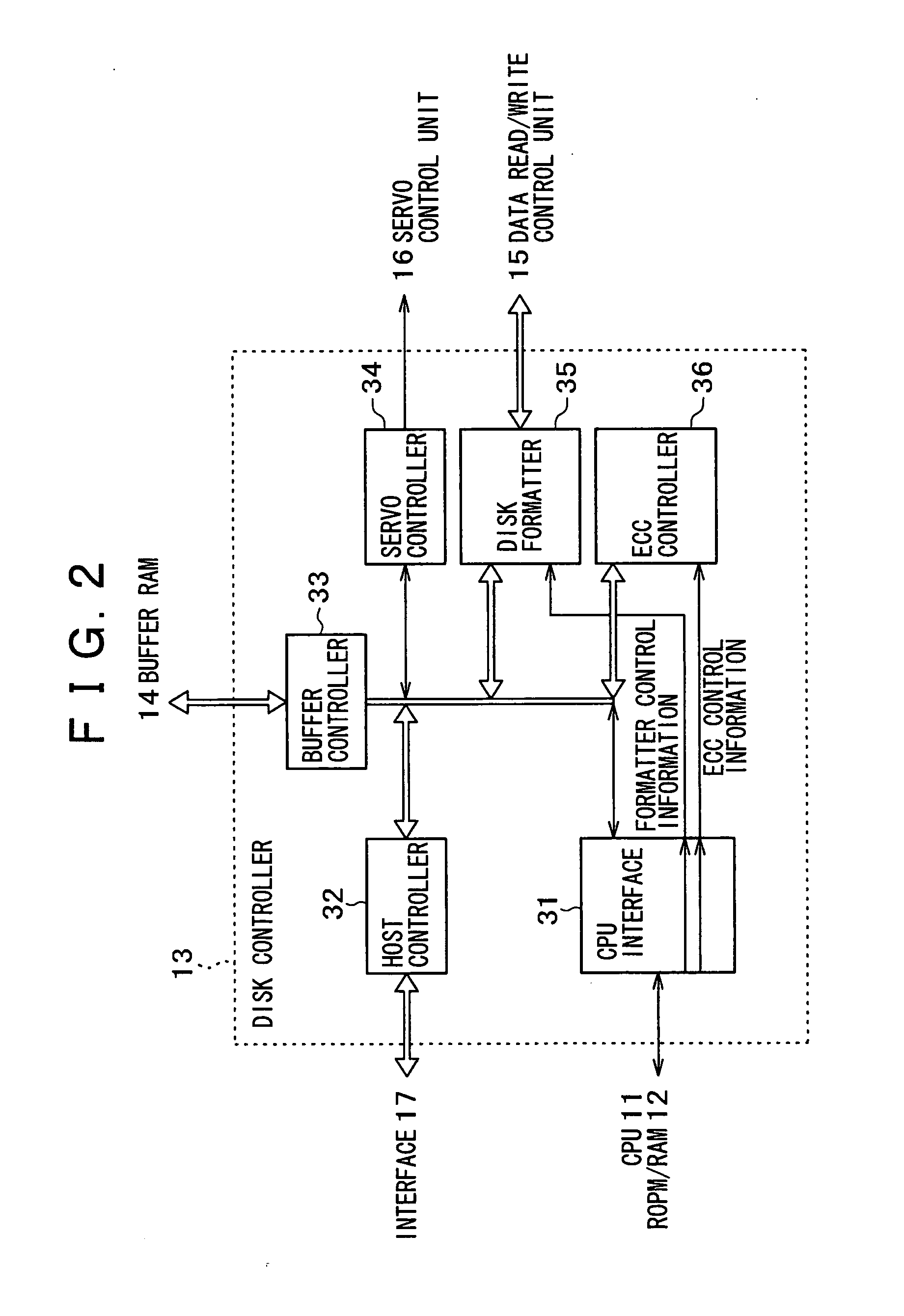
FIG. 1 schematically illustrates the overall configuration of the HDD (Hard Disk Drive) 10 in an embodiment of the present invention.

As illustrated in FIG. 1, the HDD 10 includes CPU (Central Processing Unit) 11, ROM (Read Only Memory) / RAM (Random Access Memory) 12, disk controller 13, buffer RAM 14, data read / write control unit 15, servo control unit 16, and magnetic disk 21.

One or more magnetic disks 21 are provided, and the recording surface is provided on either or both sides of the magnetic disks (the front and rear faces of the disks). A head is disposed above each of the recording surfaces. FIG. 1 shows a state in whi...


PUM

PropertyMeasurementUnit
stabilityaaaaaaaaaa
speedaaaaaaaaaa
magneticaaaaaaaaaa

Abstract

A stable system is provided wherein the influence of disturbance or the like can be reduced. First error correcting code units and second error correcting code units are used, and thereby a wider range of random errors and burst errors are made correctable to avoid retry operation. Thus, stable data reproduction is carried out without degrading transfer rate. Further, the constitution of error correcting blocks is set so that when a head is moved to some track during seek operation, a sector having the second error correcting code recorded therein is the first sector to be read.

Description

BACKGROUND OF THE INVENTION Description of Related Art [Patent Document 1] Japanese Unexamined Patent Publication No. 2000-276856. [Patent Document 2] Japanese Unexamined Patent Publication No. 2000-278645. The present invention relates to a data recording / reproducing device and a data recording / reproducing method for a randomly accessible recording medium, a computer program, and a recording medium. More particularly, the present invention relates to a technique for a disk-type recording medium, such as a hard disk, wherein data read / write operation is performed by sweeping a magnetic head over a magnetic disk as a medium. In addition, the present invention relates to a technique for shortening the time required to access a desired data storage location, as well as to recording and reproducing data with stability. As information technology develops, such as information processing and information communication, reuse of information created and edited in the past has become neces...

Claims


Application Information

Patent Timeline
Patent Type & Authority Applications(United States)
IPC IPC(8): G06F3/06G11B20/12G11B20/18
CPCG06F3/0601G06F2003/0697G11B20/1217G11B20/1866G11B2020/10916G11B2220/2516G11B2020/1232G11B2020/1238G11B2020/1287G11B2020/1292G11B2020/1294G11B2020/1222G11B20/18
Inventor NAKAGAWA, TOSHIYUKIMURAOKA, YOSHIOETO, HIROAKI
Owner SONY CORP
Learn More