
Power amplifier

Inactive Publication Date: 2005-02-10
NTT DOCOMO INC
View PDF5 Cites 58 Cited by
  • Summary
  • Abstract
  • Description
  • Claims
  • Application Information

AI Technical Summary

Benefits of technology

[0011] A general object of the present invention is to provide a power amplifier which can provide continuous output power for constant envelope signals, and can amplify highly efficiently for amplitude-variable signals, and can provide continuous average output power.
[0012] Another object of the present invention is to provide a highly efficient power amplifier in which amplitude-variable output signals can be generated with small distortion and high efficiency.
[0016] In a power amplifier according to the present invention, output power can be a continuous function of input power, wherein highly efficiently controlled transmission power having continuous levels is obtained.
[0017] In a power amplifier according to one embodiment of the present invention, non-linear input-output characteristics of each power amplifying unit can be compensated for, to obtain equivalent linear amplifying units. And the equivalent linear amplifying units can be selectively combined in response to instantaneous power of an input signal, to provide a linear and highly efficient power amplifier. Accordingly, even an amplitude-variable signal can be highly efficiently and linearly amplified. Further, a power amplifier using N power amplifying units can extend a highly efficiently amplifiable input / output power range by increasing the value of N. This merit is especially advantageous when amplifying amplitude-variable signals having a large peak-to-average power ratio. In this case, by adjusting the average power of the input signals, the output signal average power can be continuously controlled.
[0018] In a power amplifier according to another embodiment of the present invention, by controlling the number of operating saturation amplifying units in response to an amplitude of a received modulation signal, an AM transmission output signal or a QAM transmission output signal can be generated. Since each of the saturation amplifying units amplifies an constant envelope signal from a local oscillator only, the amplification can be performed highly efficiently. Therefore, the total efficiency of the power amplifier becomes high. Further, by increasing the number of the saturation amplifying units or providing a linear amplifying unit for compensating for an error component, transmission output signals with low distortion can be attained.

Problems solved by technology

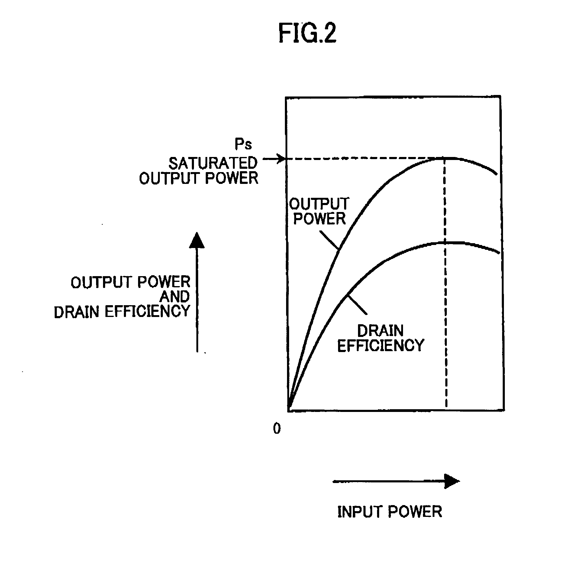
When the output power approaches the saturation output power Ps, high efficiency is obtained, but the input-output characteristics becomes significantly non-linear.
On the other hand, in an area where the input / output powers are small, the input-output characteristics become linear, but the efficiency is significantly degraded.
However, for amplitude-variable signals, transmission power levels become discrete, and there is a problem that a continuous output power level cannot be attained.
When power amplifying amplitude-variable signals using this conventional power amplifier, transmission output signals have large distortion due to non-linearity of each of the Class F amplifying circuits.
Further, even if the transmission output signals are averaged, the thus obtained average power levels are still discrete, and no continuous average power level can be attained.

Method used


Image

  • Power amplifier
  • Power amplifier
  • Power amplifier

Examples


first embodiment

[0045] First Embodiment

[0046]FIG. 4 schematically illustrates a power amplifier 101 according to a first embodiment of the present invention. The power amplifier 101 comprises N power amplifying units 112 (N is an integer larger than 1), N amplitude adjusters 113, an output combining unit 114 and a controller 115. In this embodiment, the amplitude controlling unit 15 comprises the N amplitude adjusters 113 and the controller 115. Power of a transmission input signal 110 is adjusted by each of the amplitude adjusters 113, and each adjusted power level is supplied to the respective one of the power amplifying units 112. The controller 115 controls a power adjusting coefficient of each of the amplitude adjusters 113, and turns on / off each of the N power amplifying units, in response to the input signal 110. The output combining unit 114 combines output signals supplied from power amplifying units 112 that are operating (turned on) to make a power sum, and outputs it as a transmission o...

second embodiment

[0057] Second Embodiment

[0058]FIG. 5 shows a power amplifier 102 according to a second embodiment of the present invention. The power amplifier 102 is the same as the power amplifier 101 except that the power amplifier 102 comprises pre-distorters (PDs) 116 inserted between the amplitude adjusters 113 and the power amplifying units 112. The N pre-distorters, PD 116 and the corresponding N power amplifying units 112 constitute N equivalent linear amplifiers 117. Each of the equivalent linear amplifiers 117 has the same gain G.

[0059]FIG. 9 shows a graph illustrating input-output characteristics (curve a) of each equivalent linear amplifier 117 and input-output characteristic (curve b) of the power amplifying unit 112. The saturation output power of the power amplifying unit 112 is represented by Ps, and the equivalent linear amplifying unit 117 can have a linear input-output characteristic in a range where its output varies from 0 to Ps. The efficiency of the equivalent linear amplif...

third embodiment

[0066] Third Embodiment

[0067]FIG. 6 shows a power amplifier 103 according to a third embodiment of the present invention. The power amplifier 103 is the same as the power amplifier 102 except that in the power amplifier 103, the non-linearity of each of the power amplifying units 112 is compensated for by the amplitude adjusters 113 instead of the PDs 116. In this embodiment, power adjustment amounts for the amplitude adjusters 113 comprise a first adjustment amount for the equivalent linear amplifier 119 for compensating for the non-linearity of the power amplifying units 112, and a second adjustment amount for so adjusting that the transmission input signal is within an input range of the equivalent linear amplifier 119.

[0068] As for each amplitude adjuster 113, an equivalent linear amplifier 119 having a gain of G, a maximum output of Ps is formed, and the second adjustment amount is adjusted in the same manner as the second embodiment shown in FIG. 5. The power of the transmiss...


PUM


Abstract

A power amplifier (1) for receiving and amplifying an input signal (10) and outputting an output signal (11) is disclosed. The power amplifier comprises: N power amplifying units (12) (N is an integer larger than 1) connected in parallel so as to output amplified signals in response to the input signal (10); an output combining unit (14) for combining the output signals from the N power amplifying units (12) and outputting a combined signal as the output signal (11) of the power amplifier; and an amplitude controlling unit (15) for selectively turning ON each of the N power amplifying units (12) based on an amplitude of the input signal (10). In the power amplifier, the amplitude controlling unit (15) may comprise N amplitude adjusters (113) connected in parallel for adjusting the amplitude of the input signal (110) of the power amplifier; and a controller (115) for selectively turning ON each of the N power amplifying units (112) and controlling the amplitude adjusters (113) so that an amplitude of the output signal (111) becomes a substantially continuous function with respect to the amplitude of the input signal (110). The power amplifier may further comprise a local oscillator (222) outputting an constant envelope signal, receiving a modulation signal (210) as the input signal of the power amplifier and outputting an amplified modulated signal (211) as the output signal of the power amplifier; wherein the N power amplifying units comprise N saturation amplifying units connected in parallel so as to amplify the constant envelope signal from the local oscillator; and the amplitude controlling unit comprises an amplifying controller (215) for selectively turning ON each of the N saturation amplifying units (212) based on an amplitude of the modulation signal (210).

Description

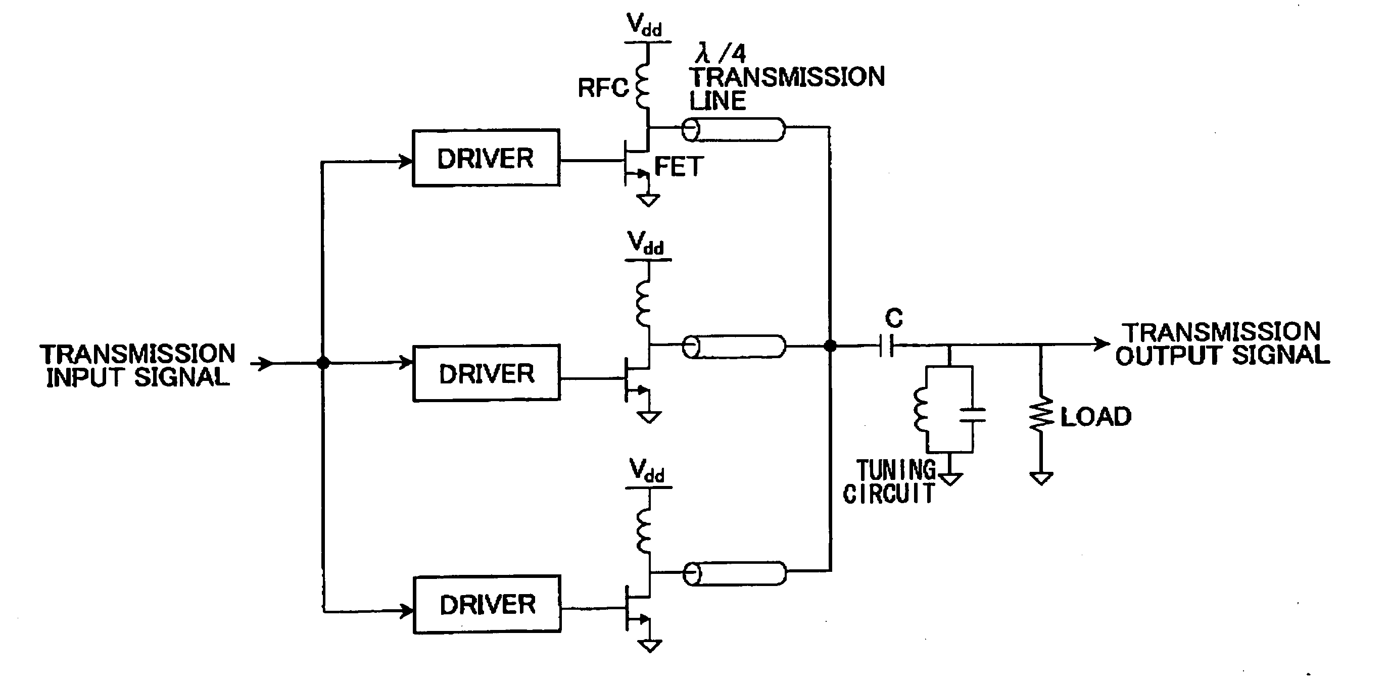
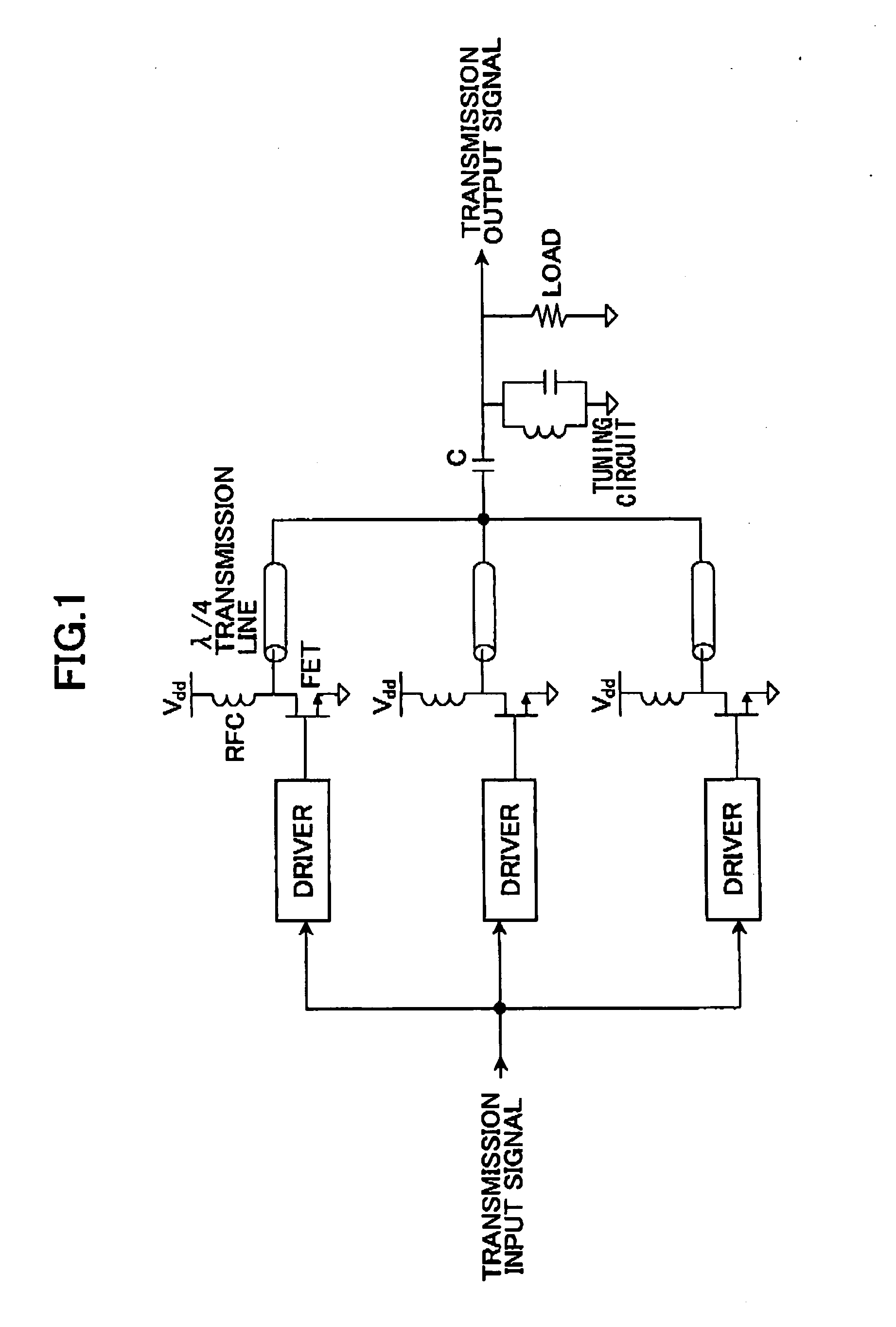
BACKGROUND OF THE INVENTION [0001] The present invention generally relates to power amplifiers, and, more particularly, to a power amplifier which can control its output power to make it continuous, and to a power amplifier which can highly efficiently amplify modulated signals. [0002] One conventional power amplifier is known in the art, in which a plurality of power amplifying units are used in parallel for performing efficient amplification, as shown in “Alireza Shirvani, David K. Su, and Bruce A. Wooley, “A CMOS RF Power Amplifier With Parallel Amplification for Efficient Power Control, “IEEE JOURNAL OF SOLID-STATE CIRCUITS. VOL. 37, NO. 6, JUNE 2002”. [0003]FIG. 1 shows a basic structure example of a conventional power amplifier. This conventional power amplifier comprises a plurality of Class F amplifying circuits. Each of the Class F amplifying circuits comprises an FET (Field Effect Transistor), a λ / 4 transmission line connected to a drain of the FET, a capacitor C, a tuning...

Claims


Application Information

Patent Timeline
IPC IPC(8): H03F1/02H03F1/32H03F3/20H03F3/217H03F3/24H03F3/68H03F3/72
CPCH03F1/0277H03F2200/75H03F3/72H03F3/2178H03F1/32H03F3/20
Inventor CHEN, NINGSUZUKI, YASUNORIHIROTA, TETSUOYAMAO, YASUSHI
Owner NTT DOCOMO INC
Learn More