
Fixing device, image forming apparatus using the same and process cartridge

a technology of fixing device and image forming apparatus, which is applied in the direction of electrographic process apparatus, instruments, optics, etc., can solve the problems of triboelectric charging of fixing members, contamination of transfer materials, and friction between both members, so as to reduce the occurrence of contamination

Active Publication Date: 2005-02-03
RICOH KK
View PDF6 Cites 58 Cited by
  • Summary
  • Abstract
  • Description
  • Claims
  • Application Information

AI Technical Summary

Benefits of technology

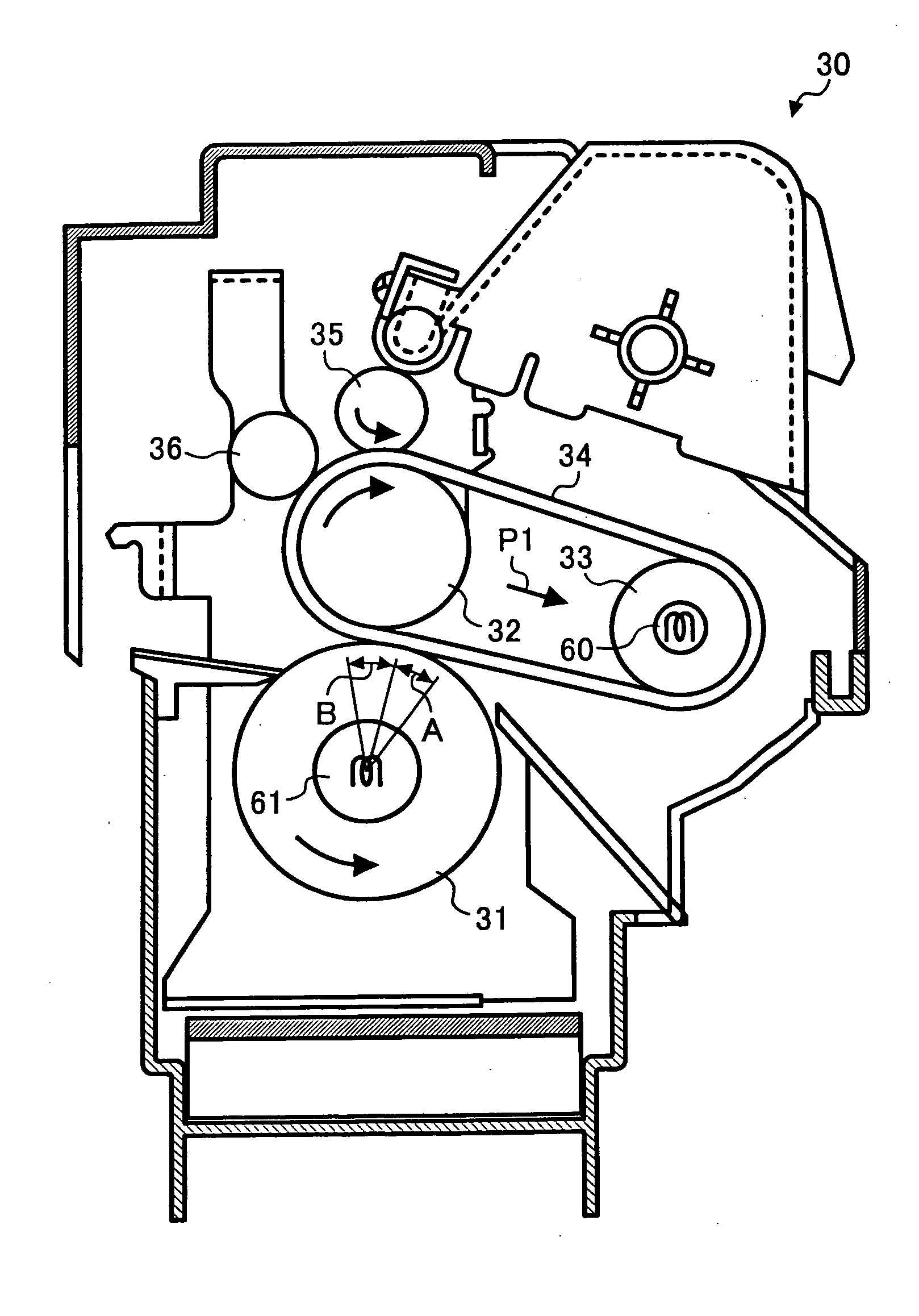
Accordingly, an object of the present invention is to provide a fixing device and an image forming apparatus having a structure which can reduce occurrence of contamination to a transfer material by surely preventing toners from transferring to the heating member included in the fixing device to produce quality images.

Problems solved by technology

Further, when the transferred toner particles contact the transfer material again while the transferred toner particles are still in a fusion state, the toner particles may be transferred thereto, resulting in contamination of the transfer material.
One of the causes of the electrostatic offset is triboelectric charging of fixing members, i.e., heating members and pressing members.
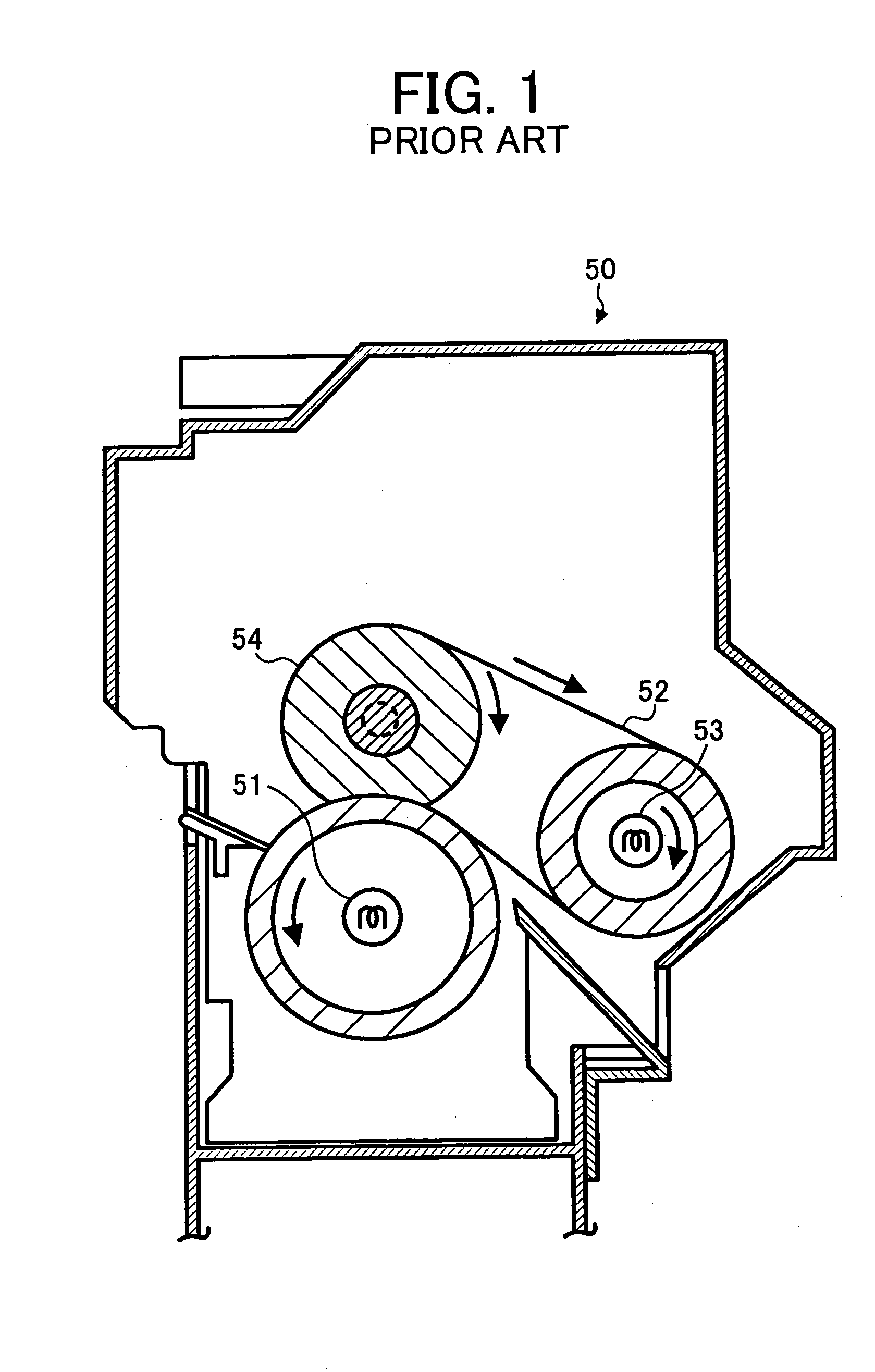
That is, due to the difference in the processing precision levels between a heating member and a pressing member, the pressing member and the heating member may move at different speeds and then friction between both members may occur.
In addition, the causes of triboelectirc charging of the heating member are not only the difference in the processing precision levels.
However, a problem occurs to even a fixing device having a cleaner when small sized recording media such as post cards are transferred in a row.
This relatively high temperature is high enough to fuse the toner particles collected by and located on the cleaner and the fused toner particles are attached to the fixing belt, resulting in contamination of recording media.
In addition, it is inevitable that a fixing device having a cleaner is complicated and increased in size.
Conventional toners prepared by kneading and pulverizing have irregular forms and therefore are disadvantageous with regard to particle diameter distribution, fluidity and transferability.
Further, such irregular form toners have prongs to which charges are easily concentrated, resulting in deterioration of charge ability of the toner.
As discussed above, triboelectric charging causing the electrostatic offset is mainly due to the difference in linear speeds among the members used for fixing and the transfer material, however currently it is practically impossible to eliminate the speed difference.
Thus, the toner attraction caused by the triboelectirc charging mentioned above resulting from the difference in linear speeds of the heating member, the pressing member and the transfer material cannot be prevented by the fixing device using a pressing member having a predetermined surface resistivity.
However, polymerized toners tend to be affected by environmental factors such as humidity.

Method used


Image

  • Fixing device, image forming apparatus using the same and process cartridge
  • Fixing device, image forming apparatus using the same and process cartridge
  • Fixing device, image forming apparatus using the same and process cartridge

Examples


example 1

(Toner 1)

(Manufacturing Example of Polyesters for Addition)

The following components were contained in a reaction container having a condenser, a stirrer and a nitrogen introducing tube and polyadded for 10 hours at 210° C. under normal pressure.

Adduct of bisphenol A with 2 moles of ethylene oxide690Terephthalic acid230

Then the reaction was further continued for 5 hours under a reduced pressure of from 10 to 15 mmHg. Subsequent to cooling down to 160° C., 18 parts of phthalic anhydride were added thereto to perform a reaction for 2 hours. Thus, unmodified polyester (a) having a weight average molecular weight Mw of 85,000 was prepared.

(Manufacturing Example of Prepolymer)

The following components were contained in a reaction container having a condenser, a stirrer and a nitrogen introducing tube and reacted for 8 hours at 230° C. under normal pressure.

Adduct of bisphenol A with 2 moles of ethylene oxide800Isophthalic acid160Terephthalic acid60Dibutyl tin oxide2

Then the ...

example 2

(Toner 2)

(Preparation of Magenta Master Batch Particle)

The following components were stirred by a flusher.

Water600Pigment Red 57 wet cake (50% solid portion)200

Then, after 1,200 parts of a polyester resin having an acid value of 3 mgKOH / g, a hydroxyl value of 25 mgKOH / g, a number average molecule weight Mn of 3,500, a ratio (Mw / Mn) of a weight average molecular weight Mw to the number average molecular weight of 4.0, and a glass transition temperature (Tg) of 60° C. were added to the mixture, the mixture was kneaded for 30 minutes at 150° C. Further, 1,000 parts of xylene were added thereto and the mixture was kneaded for one hour. Subsequent to removal of water and xylene, the resultant was roll-cooled and pulverized and subject to 3 roll milling twice. Consequently, a magenta color master batch colorant MB1-M having an average particle diameter of about 0.2 μm was obtained.

(Manufacturing Example of a Prepolymer)

The following components were contained in a reaction cont...

example 3

(Toner 3)

(Manufacturing Example of a Prepolymer)

The following components were contained in a reaction container having a condenser, stirrer and a nitrogen introducing tube and reacted for 8 hours at 220° C. under normal pressure.

Adduct of bisphenol A with 2 moles of ethylene oxide755Isophthalic acid195Terephthalic acid15Dibutyl tin oxide4

Then the reaction was further continued for 5 hours under a reduced pressure of from 50 to 100 mmHg while dehydrating. Subsequent to cooling down to 160° C., 10 parts of phthalic anhydride were added thereto to perform a reaction for 2 hours. Subsequent to further cooling down to 80° C., 170 parts of isophorone diisocyanate were added thereto in ethyl acetate to react for another 2 hours. Consequently, a prepolymer (3) having a weight average molecular weight of 25,000 containing an isocyanate group was prepared.

(Manufacturing Example of the Toner)

The following components were set in a beaker and stirred and dissolved.

Prepolymer (3)15....


PUM


Abstract

A fixing device configured to fix the toner image borne on a side of a transfer material. The fixing device including a heating member configured to heat the toner image while contacting the toner image borne on the transfer material and a pressing member configured to press the transfer material to the heating member. Further, a surface of the pressing member has a property such that the toner particles forming the toner image are not electrostatically repelled from the transfer material toward the heating member.

Description

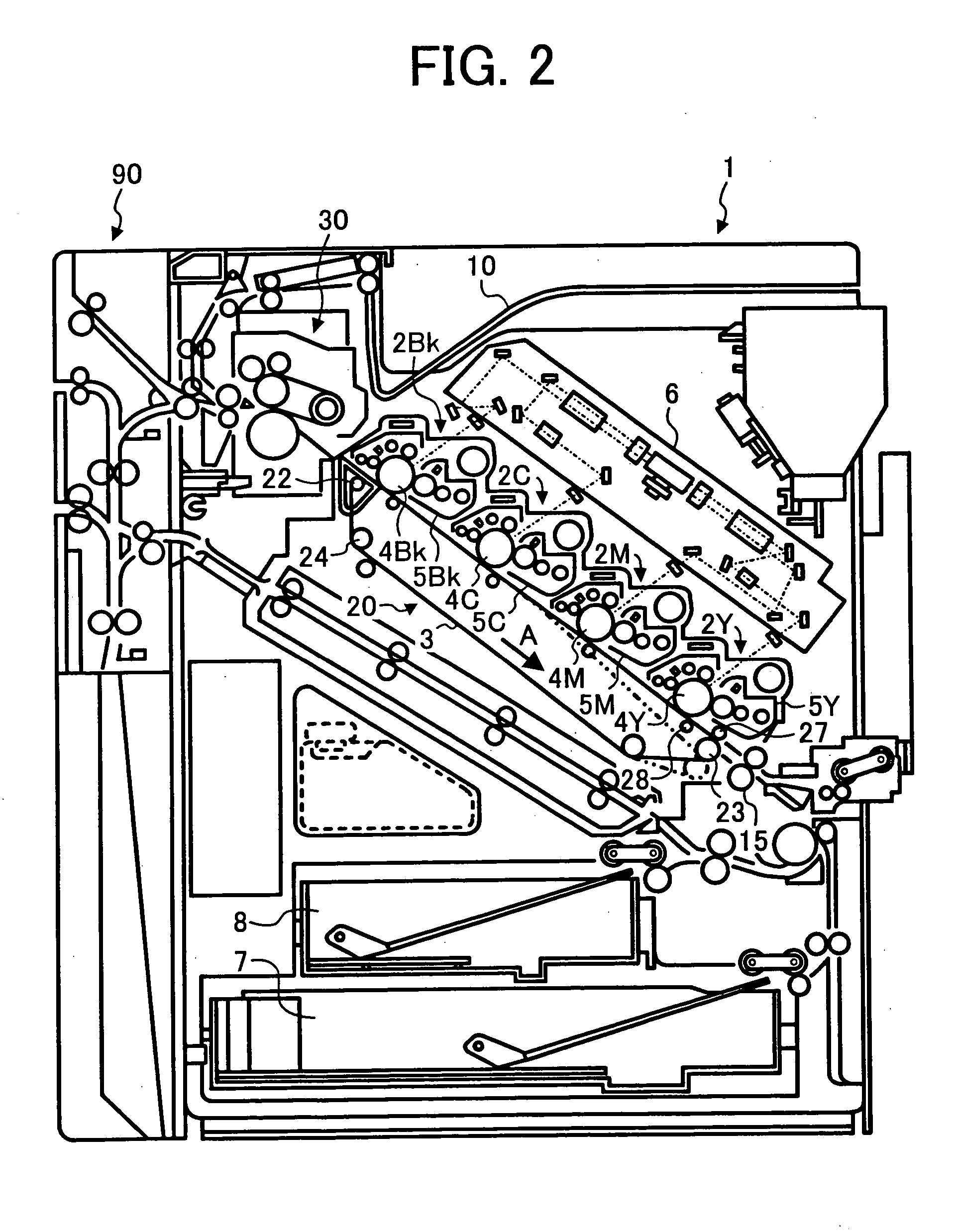
BACKGROUND OF THE INVENTION 1. Field of the Invention The present invention relates to a fixing device to fix a toner image onto a transfer material which is developed from a latent image bearing member. The present invention also relates to an image forming apparatus using the fixing device and a process cartridge detachably attached to the image forming apparatus. 2. Discussion of the Background An electrophotographic developing device is typically used for image forming methods such as electrophotography, electrostatic recording and electrostatic printing. The image forming methods typically include the following processes: (1) an electrostatic latent image formed on an image bearing member, such as a photoreceptor or a dielectric material, is developed with a developer including a toner to form a toner image on the image bearing member (developing process); (2) the toner image is transferred on a receiving material, such as a receiving paper, optionally via an intermediate...

Claims


Application Information

Patent Timeline
Patent Type & Authority Applications(United States)
IPC IPC(8): G03G15/20
CPCG03G2215/2048G03G15/206G03G2215/2032
Inventor YOSHINAGA, HIROSHI
Owner RICOH KK
Learn More