
Process for the manufacture of 1,3,3,3-tetrafluoropropene

a technology of tetrafluoropropene and tetrafluoropropene, which is applied in the preparation of halogenated hydrocarbons, physical/chemical process catalysts, hydrogen halide split-off, etc., can solve the problems of not being economical relative to the product yield of known processes, and certain chlorofluorocarbons might be detrimental to the earth's ozone layer

Active Publication Date: 2005-01-27
HONEYWELL INT INC
View PDF3 Cites 126 Cited by
  • Summary
  • Abstract
  • Description
  • Claims
  • Application Information

AI Technical Summary

Benefits of technology

[0015] Any water in the hydrogen fluoride (HF) will react with and deactivate the fluorination catalyst. Therefore substantially anhydrous hydrogen fluoride is preferred. By “substantially anhydrous” it is meant that the HF contains less than about 0.05 weight % water and preferably contains less than about 0.02 weight % water. However, one of ordinary skill in the art will appreciate that the presence of water in the HF can be compensated for by increasing the amount of catalyst used.

Problems solved by technology

In recent years, there has been widespread concern that certain chlorofluorocarbons might be detrimental to the Earth's ozone layer.
It has been determined that these known processes are not economical relative to their product yield.

Method used


Image

  • Process for the manufacture of 1,3,3,3-tetrafluoropropene
  • Process for the manufacture of 1,3,3,3-tetrafluoropropene

Examples


examples 1-18

[0024] The fluorination reaction was conducted in a 2.54 cm diameter, 81 cm long Monel® reactor. The reactor was heated with an electric furnace. The reactants of HCFC-1233zd (>99.9% purity), anhydrous HF and, optionally, chlorine, were fed to the reactor at constant flow rates. The flow rate of the chlorine was measured using a Hasting mass flow meter and controller. The flow rate for the reactants, HCFC-1233zd and HF, were controlled and measured by Honeywell PlantScape DCS (Distributive Control System) and confirmed by the weight change in the respective source cylinders.

[0025] The reactor output was sampled directly into an in-line GC, i.e. a Perkin Elmer 8500 gas chromatograph, using a Fluorocol column and FID detector, so that the amounts of organic species exiting the reactor could be determined during the operation of the process.

[0026] The reaction conditions for Examples 1-18 and corresponding experimental results are listed below in Tables 1 and 2, respectively. Contact...

example 19

[0035] A starting material consisting of 91.5 GC area % 1,1,1,3,3-pentafluoropropane (HFC-245fa) and 0.0121 GC area % HFC-1234ze was bubbled through a 2.0 wt % potassium hydroxide (KOH) solution. The organic mixture resulting from the combination was collected and analyzed by GC equipped with a FID. The mixture contained 15.455 GC area % HFC-1234ze.

example 20

[0036] To a reaction setup consisting of a 3-neck round bottom flask (5 L), mechanical agitator, reflux condenser, and low temperature cold trap was added to 3000 ml acetonitrile and 9.9 moles (504 g) of KOH pellets. After mixing, 5.1 moles (684 g) of 80 GC area % HFC-245fa / 20 GC area % HCFC-1233zd was added through a dip leg. The reagents were heated slowly with vigorous agitation. Reaction was observed at about 60° C. The crude product was collected in the cold finger. The crude material was analyzed by GC and consisted of about 62.0 GC area % HFC-1234, 20.9 GC area % HFC-245fa, and 16.2 GC area % HCFC-1233zd.


PUM

PropertyMeasurementUnit
Temperatureaaaaaaaaaa

Abstract

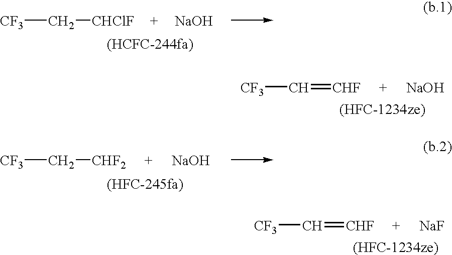
The invention provides an economic process for the manufacture of 1,3,3,3-tetrafluoropropene (HFC-1234ze) by a two stage process. A hydrofluorination of 1-chloro-3,3,3-trifluoropropene (HCFC-1233zd) into 1-chloro-1,3,3,3-tetrafluoropropane (HCFC-244fa) and 1,1,1,3,3-pentafluoropropane (HFC-245fa) is conducted, followed by the dehydrochlorination of HCFC-244fa and dehydrofluorination of HFC-245fa into HFC-1234ze.

Description

BACKGROUND OF THE INVENTION [0001] This invention relates a process for the manufacture of 1,3,3,3-tetrafluoropropene (HFC-1234ze). More particularly, the invention pertains to a process for the manufacture of HFC-1234ze by a two stage vapor phase process. The process comprises a hydrofluorination of 1-chloro-3,3,3-trifluoropropene (HCFC-1233zd) into 1-chloro-1,3,3,3-tetrafluoropropane (HCFC-244fa) and 1,1,1,3,3-pentafluoropropane (HFC-245fa), followed by the dehydrochlorination of HCFC-244fa and dehydrofluorination of HFC-245fa. [0002] Traditionally, chlorofluorocarbons (CFCs) like trichlorofluoromethane and dichlorodifluoromethane have been used as refrigerants, blowing agents and diluents for gaseous sterilization. In recent years, there has been widespread concern that certain chlorofluorocarbons might be detrimental to the Earth's ozone layer. As a result, there is a worldwide effort to use halocarbons which contain fewer or no chlorine substituents. Accordingly, the production...

Claims


Application Information

Patent Timeline
IPC IPC(8): B01J21/18B01J27/10C07C17/04C07C17/20C07C17/25C07C19/08C07C21/18
CPCB01J21/18B01J27/10C07C17/04C07C17/206C07C17/25C07C19/08C07C21/18C07C19/10
Inventor TUNG, HSUEH SUNGJOHNSON, ROBERT C.MERKEL, DANIEL C.
Owner HONEYWELL INT INC
Learn More