Eureka AIR delivers breakthrough ideas for toughest innovation challenges, trusted by R&D personnel around the world.

High defiberization chip pretreatment

Active Publication Date: 2005-01-20
ANDRITZ INC
View PDF11 Cites 25 Cited by
  • Summary
  • Abstract
  • Description
  • Claims
  • Application Information

AI Technical Summary

Benefits of technology

[0006] It is a further object that this high degree of axially separated fibers be achieved while retaining the benefits of the apparatus and method described in International Application PCT / US98 / 14710, i.e., maceration of chip structure with minimal damage under pressurized inlet conditions, reduction in refiner energy consumption, good extractives removal, improved chip size distribution for refiner stability, and improved impregnation of chemicals, while achieving significant further reduction in required specific energy for producing satisfactory quality papermaking pulp.
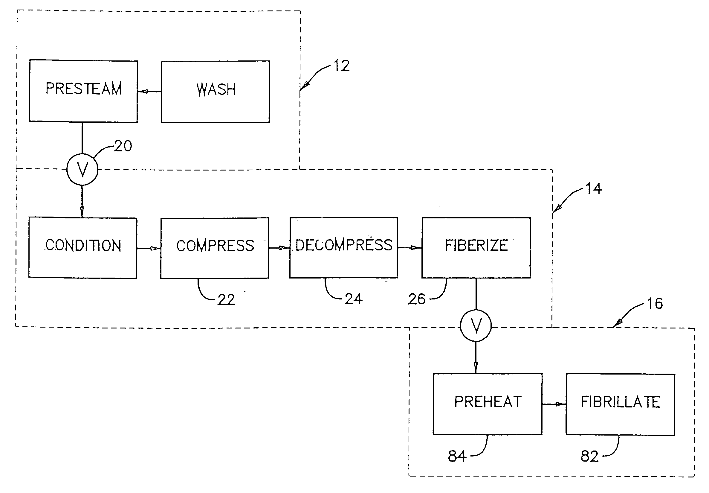
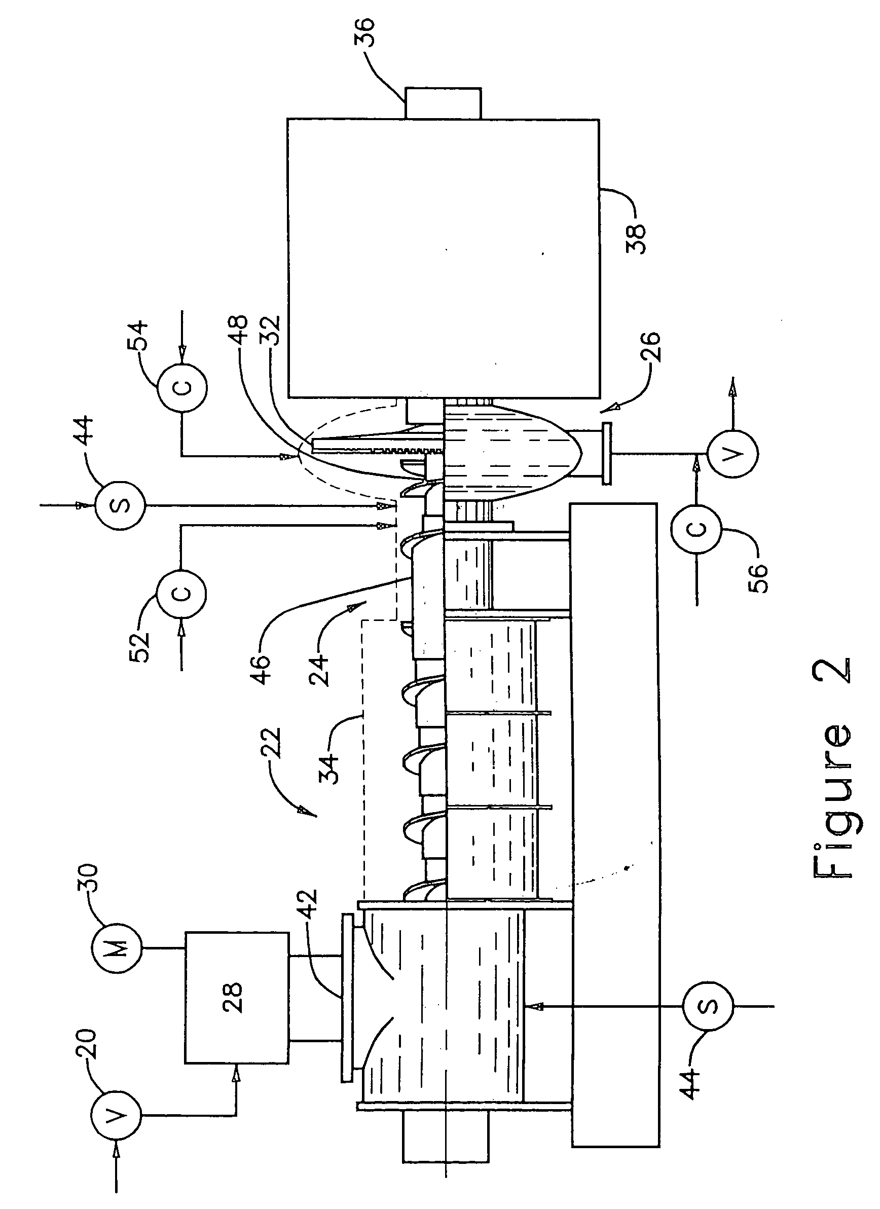
[0013] It can be appreciated that, although the use of a pressurized pretreatment device, such as a pressurized screw, is known from the RT Pressafiner method, and certainly fibrillating chip material in a primary or secondary refiner is known, a novel and significant aspect of the present invention is the inter-positioning of a highly effective but low energy consuming fiberizing device in the pretreatment process, e.g., in the form of a mechanical refiner, which achieves high fibration without expending the energy required for substantial fibrillation. A premise of the invention is to maximize separation of the fibration and fibrillation steps of the thermomechanical refining process. The latter step., is the most energy consuming, and requires efficient energy transfer at high intensity conditions to minimize total energy consumption.
[0015] The present invention achieves a much higher level of axial fiber separation as compared with conventional chip presses, even as improved by the RT Pressafiner pretreatment. Fiberizing in a pretreatment fiberizing device permits fiber orientation while the fibers experience the stress-strain cycles necessary to axially separate the fibers. Pressurization permits chip size reduction in the pressing and fiberizing zones with minimal damage to the chip structure. There is a gradual transition from the pressing zone to primary refining, and this achieves axial fiber separation in a controlled manner. Moreover, higher levels of extractive removal can be achieved due to both the pressurized environment and a reduced size distribution. Furthermore, water or chemical liquor impregnation is improved.
[0016] Primary refining (fibrillating) in the production subsystem is improved, in that significantly lower specific energy is required for a given freeness, due to the high level of axially separated fibers feeding the primary refiner. This permits the lowest installed energy requirement for a given plant capacity. Moreover, increased primary refiner capacity can result from higher available plate surface area, i.e., the breaker bar zone can be substantially reduced or eliminated because a fiber material rather than chip material is sent to the primary refiner. In addition, the primary refiner load stability is improved due to the reduction in the bulk density of the feed material. The pulp property / specific energy relationships can be adjusted by the level of chip fibration achieved in the pretreatment. Finally, the parameter windows for the RTS primary refining process can be further adjusted to optimize refining for fibrated inlet material rather than merely size reduced or intact wood chips.

Problems solved by technology

Although the RT Pressafiner pretreatment method and apparatus has been highly effective in producing axially separated fibers (i.e., separated along the grain), there appears to be an upper limit on axial separation of about 25-30 percent of the total chip mass.

Method used


Image

  • High defiberization chip pretreatment
  • High defiberization chip pretreatment
  • High defiberization chip pretreatment

Examples


example 1

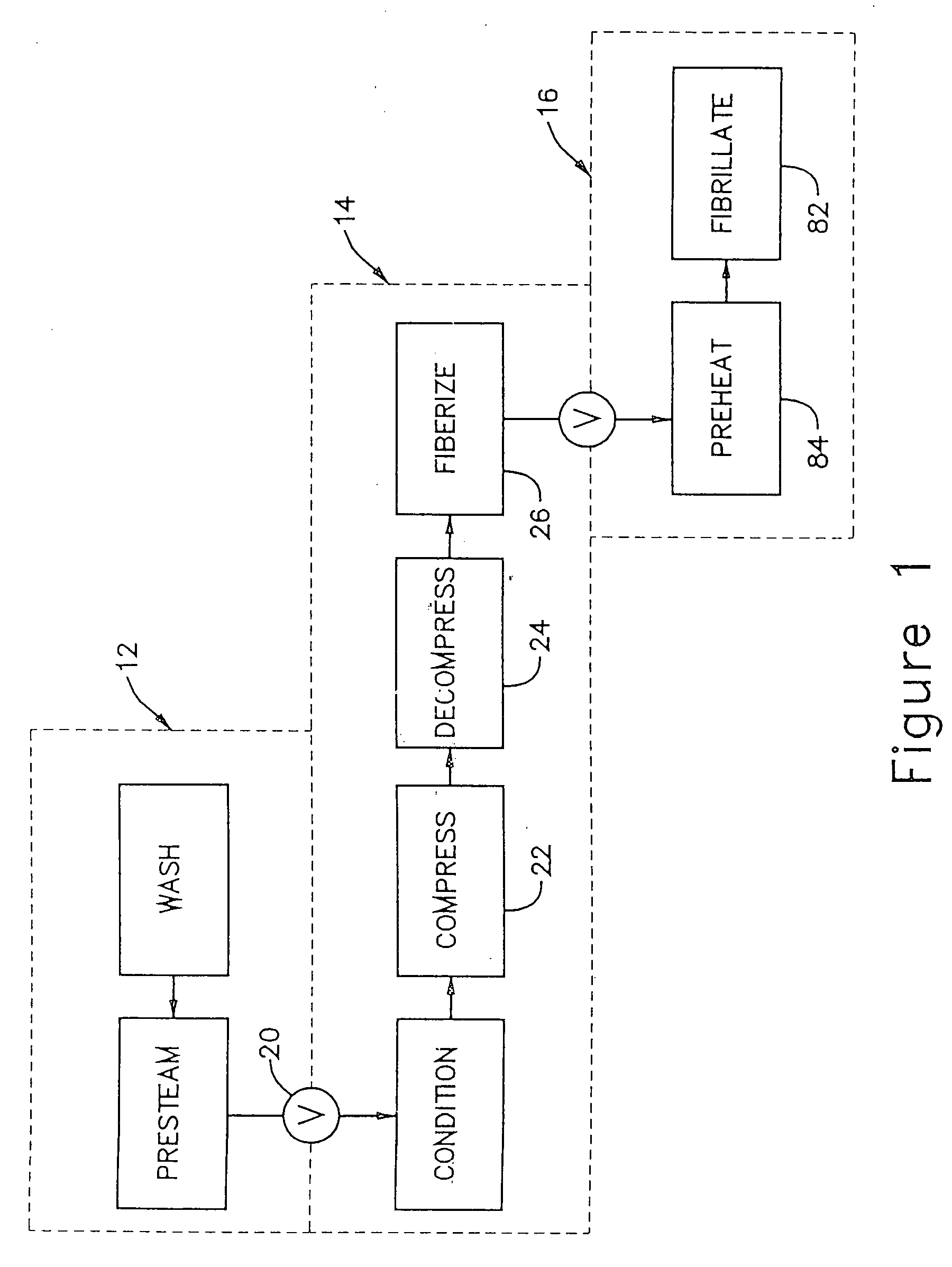
[0063]FIGS. 6-13 graphically present the results of a pilot plant investigation of a pulp papermaking system as generally depicted in FIG. 1. The wood furnish used in the study was Black Spruce. The reference system utilized the RT Pressafiner pretreatment of the type described in International Application PCT / US98 / 14710, having the conditioning and compression at elevated temperature and pressure wherein less than 25 percent of the fibers are axially separated, whereupon these pretreated chips were fed to an RTS type primary refiner operating at 2300 rpm. This reference configuration is indicated as “RT-RTS”.

[0064] The pilot system according to the present invention is represented by RTF-RTS, in which the preprocessing 12 and primary refining 16 were in the same equipment as for the reference RT-RTS runs. The number serving as the suffix to “RTF” indicates the speed of rotation of the fiberizing disc according to the invention. For both the reference runs and the runs according to...

example 2

[0068]FIG. 9 is a bar graph showing a comparison of the effect on specific energy to achieve a freeness of 200 ml when the disc rotation speed on the high intensity, primary refiner is changed. The first bar is for the reference RT-RTS run with the primary refiner running at 2300 rpm, the required energy is 2277 KWH / ODMT. Implementation of the present invention for wood chip feed material pretreatment when processed further with the primary refiner running at 2300 rpm, required 1970 KWH / ODMT. With the reference RT-RTS running with a primary refiner at 2600 rpm, the required energy is 2023 KWH / ODMT, whereas when the inventive pretreatment is employed upstream of the primary refiner running at 2600 rpm, the required energy is 1830 KWH / ODMT. These data confirm that the beneficial effect of the pretreatment according to the invention can be realized over a range of high intensity primary refining speeds.

[0069]FIG. 10 compares the tear index results for the refiner series presented in F...

example 3

[0070]FIG. 11 represents results of a further investigation in which the specific energy applied to the fiberizer refiner was reduced by approximately 40%. The fiberizer disc speed for the pretreatment system was maintained at 1500 rpm and the high intensity primary refiner maintained at 2300 rpm, but with the plate pattern intensity in the primary refiner being varied. Referring to FIG. 11, the suffix (hb) refers to primary refiner plates operating in holdback direction (low intensity) and the suffix (ex) refers to primary refiner-plates operating in expelling direction (high intensity). Each of the four refiner series produced according to the invention (RTF−) had a lower energy requirement than the reference (RT−), regardless of operating with low or high intensity plates. The pulps produced with the high intensity plates (ex) had the lowest energy requirements.

[0071]FIG. 12 compares the tear index results for the refiner series presented in FIG. 11. The three refiner series pro...


PUM

PropertyMeasurementUnit
Fractionaaaaaaaaaa
Fractionaaaaaaaaaa
Fractionaaaaaaaaaa

Abstract

A chip pretreatment process which comprises conveying the feed material through a compression screw device having an atmosphere of saturated steam at a pressure above about 5 psig, decompressing and discharging the compressed material from the screw device into a decompression region, feeding the decompressed material from the decompression region into a fiberizing device, such as a low intensity disc refiner, where at least about 30 percent of the fiber bundles and fibers are axially separated, without substantial fibrillation of the fibers. In a more specific form the invention is directed to a process for producing mechanical pulp, including the steps of fiberizing wood chip feed material in a low intensity disc refiner until at least about 30 percent of the fibers are axially separated with less than about 5 percent fibrillation, and subsequently refining the fiberized material in a high intensity disc refiner until at least about 90 percent of the fibers are fibrillated. In another form the invention combines chip fiberizing with chemical treatments, for improving the pulp property versus energy relationships.

Description

BACKGROUND OF THE INVENTION [0001] The present invention relates to the production of papermaking pulp from wood chip feed material, and particularly to mechanical refining and chemi-mechanical refining. [0002] Efforts have been ongoing for decades to improve mechanical refining techniques (including chemi-mechanical refining) for producing papermaking pulp from wood chip feed material with decreasing specific energy requirements. A significant advance toward this objective was achieved by the present inventor in the mid 1990's, by the development of the “RTS” process, as described in U.S. Pat. No. 5,776,305, granted on Jul. 7, 1998, for “Low-Resident, High-Temperature, High-Speed Chip Refining. This development was directed to the relationship between chip pre-heat environment and high consistency primary refiner conditions, whereby a window of pre-heat residence time, pre-heat saturated steam temperature (pressure) and high disc refining speed produced a noteworthy reduction in sp...

Claims


Application Information

Patent Timeline
IPC IPC(8): D21B1/02D21B1/04D21B1/12D21B1/14D21B1/16D21D1/30
CPCD21B1/16D21B1/021D21B1/02D21B1/14D21D1/30
Inventor SABOURIN, MARC J
Owner ANDRITZ INC
Why Eureka
Eureka Blog
Learn More