
Barrier coating composition for a substrate

a technology of barrier coating and substrate, applied in the field of optical construction, can solve problems such as loss of reflectivity, and achieve the effects of efficient channeling, high optical performance, and favorable durability

Inactive Publication Date: 2005-01-13
SACCOMANNO ROBERT J +1
View PDF30 Cites 24 Cited by
  • Summary
  • Abstract
  • Description
  • Claims
  • Application Information

AI Technical Summary

Benefits of technology

The present invention is generally directed to an optical construction for optical components such as hollow and solid waveguides, solid and hollow light pipes, fiber optics, prisms, microstructured sheets, curved mirrors (ellipsoidal, parabolic, etc.), plano mirrors, and other optics having topographic forms. The optical construction of the present invention is designed to maintain high optical performance and light transmission through the optical component in the presence of potentially corrosive substances including sulfur dioxide, hydrogen sulfide, nitrogen dioxide, ozone, hydrogen chloride, chlorine, organic acids and the like, which are present in the atmosphere at least in trace amounts.
The optical construction of the present invention is especially useful in optical components where a highly reflective surface composed of a metal such as silver is desired. The optical construction is further adapted to provide favorable durability and preservation of the highly reflective surface in the optical component without measurably degrading the total reflectance qualities of the optical component.
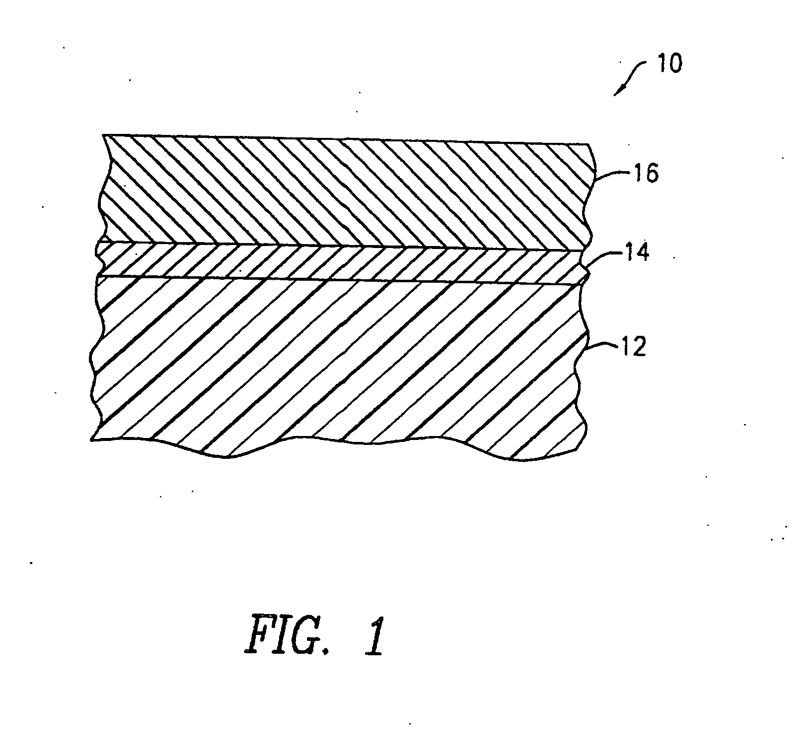
In one aspect of the invention, the optical construction generally comprises an optically transmissive substrate adapted for efficiently channeling light therethrough with a highly reflective layer composed of a highly reflective metal deposited on the surface of the substrate, and bonded thereto. Overlying the highly reflective metal layer and firmly adherently bonded thereto is a protective layer comprised of a parylene polymer film.
The parylene polymer protective layer as used in the present invention serves to isolate the reflective layer from exposure to external elements such as ambient atmosphere, corrosive substances, salt, humidity and the like. Such external elements can cause the destruction and degradation of the metal reflective layer over time through tarnishing, breakdown, delamination, or discoloration, resulting in the loss of its reflectivity. The parylene polymer protective layer further improves the reflective layer's resistance to mechanical deformation and delamination as indicated by a tape-pull test described hereinafter.
Optionally, the optical construction of the present invention can further include an adhesion-promoting layer applied between the surface of the substrate and the reflective layer to strengthen the bond therebetween. The adhesion-promoting layer as used in the present invention significantly improves the adhesion between the functional reflective metal layer and the optically transmissive substrate for improved resistance against delamination where the reflective layer physically separates from the optically transmissive substrate resulting in degraded performance and reduction in reflectivity. Further, the adhesion-promoting layer promotes uniformity and consistency in reflective properties of the reflective layer along the substrate / reflective layer interface.
In an alternative form of the invention, a waveguide structure such as a fiber optic, comprising an optically transmissive glass or polymer material, is coated with an adhesion-promoting layer of the oxide form of a metal or metalloid. A silver reflective layer is applied in contact with the adhesion-promoting layer. A protective layer of a parylene polymer film is applied over the silver reflective layer to prevent the silver from losing its high reflective luster or from delaminating or degrading due to corrosive agents in the environment such as ambient air. The preferred form of the invention forms a robust highly reflective parylene / silver / metal-oxide / waveguide structure with improved performance qualities including longer operating life.

Problems solved by technology

Such external elements can cause the destruction and degradation of the metal reflective layer over time through tarnishing, breakdown, delamination, or discoloration, resulting in the loss of its reflectivity.

Method used


Image

  • Barrier coating composition for a substrate
  • Barrier coating composition for a substrate
  • Barrier coating composition for a substrate

Examples


example 1

Experimental Tests

We obtained samples of optical quality polymethyl methylacrylate (PMMA) substrates with a reflective index of 1.49 for testing. An aluminum oxide coating was evaporatively applied to one set of samples using conventional electron beam evaporation deposition process to form an adhesion-promoting layer. The aluminum oxide source having a purity of 99.999%, was obtained from Cerac of Milwaukee, Wis. The aluminum oxide was deposited using a flow of 21.8% O2 / Ar at a total pressure of 2×10⁻⁴ Torr. The deposition rate was set at approximately 1 Å per second to produce a final thickness of about 300 Å.

A layer of silver metal was applied to the surface of each sample substrate using a conventional electron beam evaporation deposition process. The silver metal source having a purity of 99.999%, was obtained from Cerac. The silver layer was applied at a thickness of 1,000 Å at a deposition rate of from about 1.2 to 7.3 Å per second. The average deposition rate was about 3...


PUM

PropertyMeasurementUnit
reflectanceaaaaaaaaaa

Abstract

A barrier layer which protects the surface of a substrate from exposure to ambient conditions, including humidity, salt, corrosive substances, and the like, comprises a composition of a first layer of a parylene polymer over a surface portion of the substrate, a second transition layer of a mixture of the first parylene polymer and a second parylene polymer on the first layer, and a third layer of only the second parylene polymer. The second layer may be a graded layer, and the first and second parylene polymers may be selected from the group of parylene C, D, and N. An adhesion promoting layer may be between the surface of the substrate and the first layer.

Description

FIELD OF THE INVENTION The present invention relates to optical constructions, and more particularly to optical constructions having an optically transmissive substrate material coated with a robust highly reflective optical layer. BACKGROUND OF THE INVENTION Optical components such as waveguides are generally designed to confine and direct the propagation of light waves for many applications. In applications that rely on the reflection and transmission of light, significant gains in performance can be made when highly reflective materials are used in combination with optically transmissive materials. For example, a step-index fiber optic is composed of a thin strand of concentric layers of optically transmissive materials—a central optical medium (i.e., the core) and a surrounding optical medium (i.e., the cladding), the latter having a lower index of refraction. Light is channeled through the core. During transmission, the light often travels to the boundary of the core and clad...

Claims


Application Information

Patent Timeline
Patent Type & Authority Applications(United States)
IPC IPC(8): C03C17/42G02B6/02G02B6/036G02B6/12G02B6/122G02B6/132
CPCC03C17/3607C03C17/42G02B6/02G02B6/02033Y10T428/256G02B6/132G02B2006/12169G02B6/02395Y10T428/24942G02B6/1221Y10T428/31667Y10T428/31504Y10T428/3154Y10T428/31938Y10T428/31681Y10T428/31909Y10T428/31699Y10T428/31507Y10T428/31678Y10T428/31692
Inventor SACCOMANNO, ROBERT J.WEST, GARY A.
Owner SACCOMANNO ROBERT J
Learn More