Artificial synapse chip
a technology of artificial synapse and chip, which is applied in the direction of artificial respiration, prosthesis, therapy, etc., can solve the problems of permanent damage to the photoreceptor, visual impairment or blindness, and ineffective treatment for most patients
- Summary
- Abstract
- Description
- Claims
- Application Information
AI Technical Summary
Benefits of technology
Problems solved by technology
Method used
Image
Examples
example 1
[0108] Methods for stimulating cells through the nanoaperture and measuring their activity using fluorescence from Ca.sup.2+ sensitive dyes include the following: (1) voltage clamping of the cell to the aperture (applying suction via the microchannel) and varying the voltage of the buffer in the microfluidic channel; (2) chemical stimulation of the cell by pulsing a bolus of neurotransmitter to the under side of the cell; (3) microfluidic bolus of liposomes containing neurotransmitters to the aperture opening; and (4) microfluidic reservoir of engineered cells that would stimulate the neurite through the release of the transmitters.
[0109] A subconfluent layer of PC12 cells is cultured on an array of microapertures. Cell activity is measured by fluorescence microscopy with the cells loaded with a Ca.sup.+2 sensitive dye (e.g. indo-1, fura-2, fluo-3, calcium green, aequorin). The fluorescence serves both to monitor the activity of the cell directly above the aperture and to see the ef...
example 2
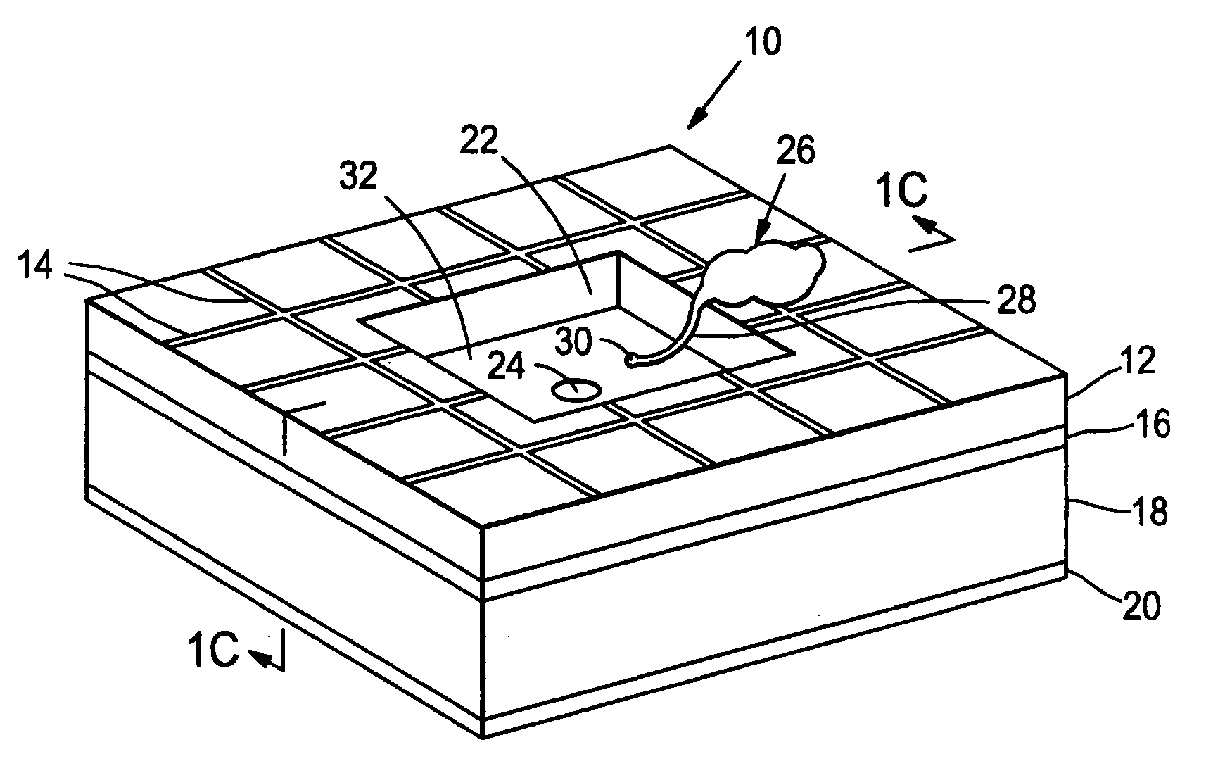
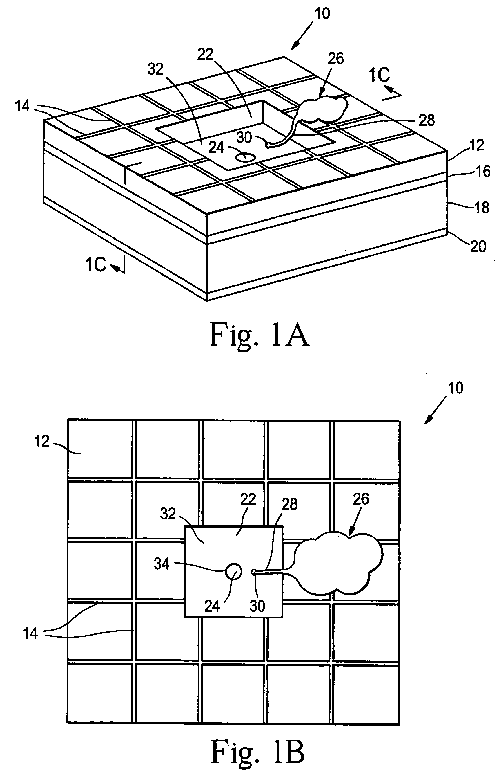
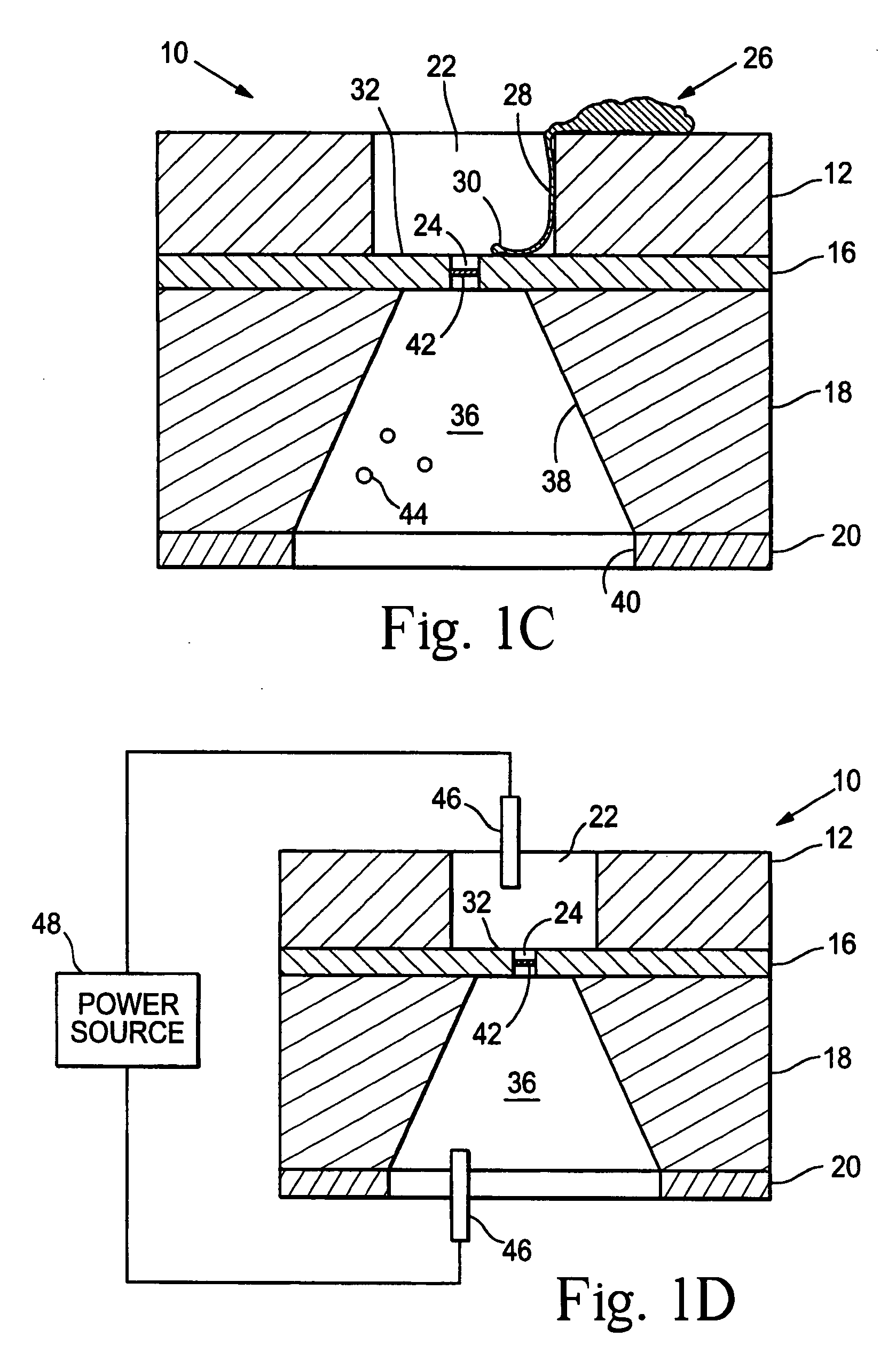
[0112] A prototype neural interface device was developed that is described in Peterman, et al., supra. The basic component in the 8'8 mm device is a small circular aperture in the side of a microfluidic channel. Using standard microfabrication techniques, a thin layer of silicon nitride (1.6.mu. thick) was deposited on a silicon wafer. Four circular apertures were etched through the silicon nitride in a 2'2 array (5.mu. diameter, 125.mu. center-to-center). The silicon wafer was then anisotropically etched through the silicon wafer, creating a thin, free standing membrane roughly 350.mu. on a side. Channels were created by lithographically patterning 25.mu. deep SU-8 photoresist over the apertures. The 50.mu. wide channels were designed with a bend to allow each channel to overlay a single aperture. The bend provides sufficient room for inlet and outlet connections to each channel. Gold electrodes for controlling electroosmotic flow are patterned inside the channels with two common g...
example 3
[0122] In another study, the prosthesis device material consisted of a combination of SU-8 photoresist (MicroChem Corp.) and PDMS. The device was prepared substantially as described in FIG. 2. To alleviate adhesion between the PDMS layers and the silicon substrate, a thin gold layer (100 nm) was deposited on a blank four-inch silicon wafer. A layer of SU-8 was spun on the gold at .about.40.mu. thick as per the manufacturer's specifications. The SU-8 was exposed to define the negative of the channels. After development, PDMS was spun on the wafer at a thickness greater than the SU-8 structures. The PDMS at this point was quite flexible and self-adhesive. The PDMS was first treated in an oxygen plasma (155 W, 60 sec) and a thin layer of SU-8 was spun onto the substrate. The SU-8 layer adhered to the PDMS, stiffened the material and limited the self-adhesion. After the SU-8 was gross exposed and hard baked, the PDMS-SU-8 bilayer was peeled from the silicon wafer as a sheet.
[0123] On a ...
PUM
| Property | Measurement | Unit |
|---|---|---|
| thickness | aaaaa | aaaaa |
| thickness | aaaaa | aaaaa |
| volume | aaaaa | aaaaa |
Abstract
Description
Claims
Application Information
 - R&D
- Intellectual Property
- Life Sciences
- Materials
- Tech Scout
- Unparalleled Data Quality
- Higher Quality Content
- 60% Fewer Hallucinations
Browse by: Latest US Patents, China's latest patents, Technical Efficacy Thesaurus, Application Domain, Technology Topic, Popular Technical Reports.
© 2025 PatSnap. All rights reserved.Legal|Privacy policy|Modern Slavery Act Transparency Statement|Sitemap|About US| Contact US: help@patsnap.com


