
Three-dimensional laminating molding device

Inactive Publication Date: 2004-09-09
RICOH PRINTING SYST
View PDF13 Cites 79 Cited by
  • Summary
  • Abstract
  • Description
  • Claims
  • Application Information

AI Technical Summary

Problems solved by technology

The powder laminating method using powders requires a removal of unnecessary powders after molding and is not suited for an office environment because the powders scatter.
However, because these methods do not use a support for supporting a mold during molding process, floating island shapes (shapes that suddenly appear in layers when laminating sliced data) or long beam shapes, such as a crossbar of a letter H, could not be formed by these methods.
Therefore, moldable shapes are restricted, and so these methods are not suited for forming complex shapes, such as practical industrial products and medical models.
However, if viscosity of the resin is high, then clogging occurs in nozzles, and on the contrary, if viscosity is low, then "dripping" occurs during photo-curing or thermosetting after lamination.
However, this method had a disadvantage that leakage light or reflected light irradiates an inkjet head, resulting in clogging of nozzles.
However, those materials have some disadvantages.
That is, these materials are brittle as a mold material, and the molds are easily broken.
Further, these materials warp from shrinkage so that dimensional stability of the molds is impaired.
However, performing the smoothing process during the laminating molding process lowers a laminating molding speed.

Method used


Image

  • Three-dimensional laminating molding device
  • Three-dimensional laminating molding device
  • Three-dimensional laminating molding device

Examples


experiment 1

[0062] Experiment 1

[0063] A total of 300 g containing 10 parts by weight of urethane acrylate (trade name: DIABEAM UK6038, available from Mitsubishi Rayon Co., Ltd.) and 90 parts by weight of neopentyl glycol hydroxypivalate ester di(meth)acrylate (trade name: KAYARAD MANDA, available from Nippon Kayaku Co., Ltd.) as a mold material, 3 parts by weight of a photo-polymerization initiator (trade name: IRGACURE 1700, available from Ciba Specialty Chemicals), and 2 parts by weight of a blue pigment (trade name: Lionel Blue 7400G, available from TOYO INK MFG. CO., LTD.) as a colorant was dispersed until a uniform mixture was obtained using a homogenizer (trade name: HG30, manufactured by Hitachi Koki Co., Ltd.) at a stirring speed of 2,000 rpm. Successively, the resultant mixture was passed through a filter to remove impurities or the like, thereby obtaining a uniform ink composition for mold. The viscosity of the ink was 9.5 mPa.multidot.s, and the surface tension of the ink was 32.5 mN...

experiment 2

[0066] Experiment 2

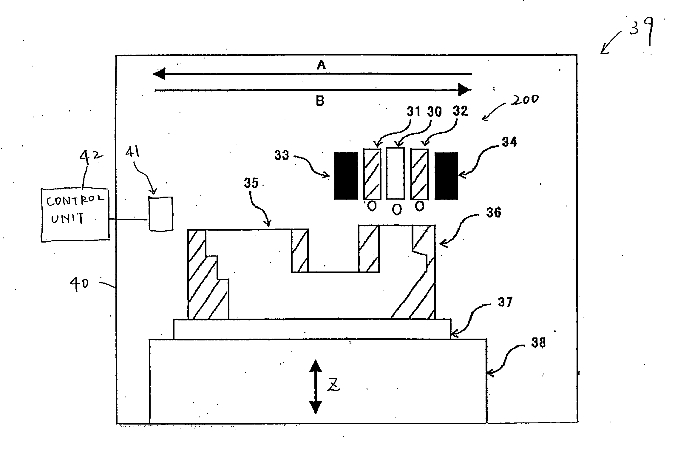
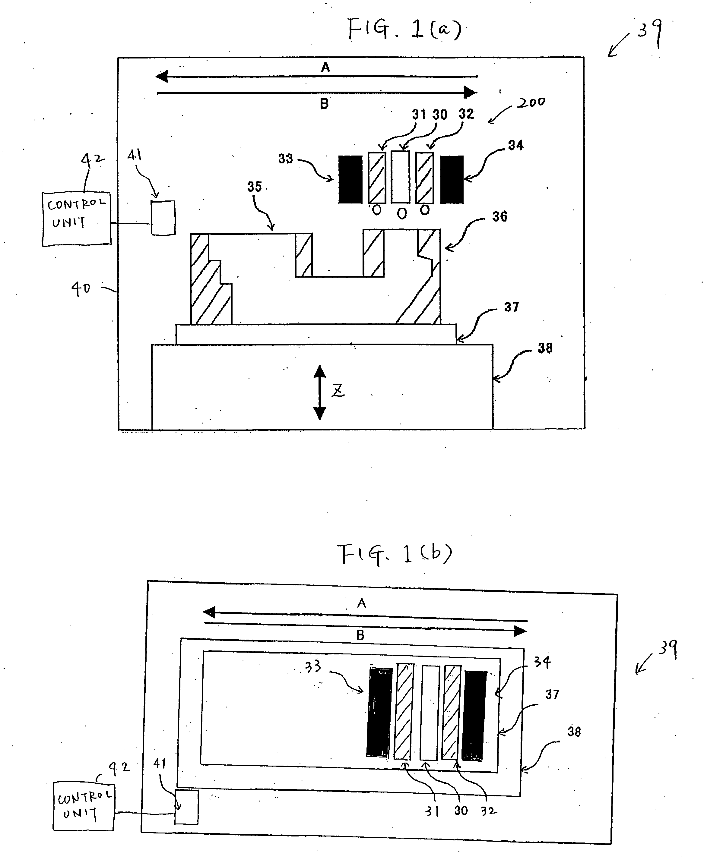
[0067] Using the same mold material and support material as that used in the experiment 1, a mold was produced while controlling the inner temperature of the molding device 39A to 70.degree. C. and curing the mold material by irradiating the mold material with 250 mJ / cm.sup.2 of light using the ultraviolet-ray irradiation devices 33, 34 (SP5-250 DB, manufactured by Ushio Inc.). The formed mold had no warp or partial deformation, and had a smooth surface.

experiment 3

[0068] Experiment 3

[0069] Using the same mold material and support material as that used in the experiment 1, a mold was formed while controlling the inner temperature of the molding device 39A to 45.degree. C. and curing the mold material by irradiating the mold material with 350 mJ / cm.sup.2 of light using the ultraviolet-ray irradiation devices 33, 34 (SP5-250 DB, manufactured by Ushio Inc.). The formed mold had no warp or partial deformation. However, the surface slightly lacked smoothness.


PUM

PropertyMeasurementUnit
Temperatureaaaaaaaaaa
Coloraaaaaaaaaa
Melting pointaaaaaaaaaa

Abstract

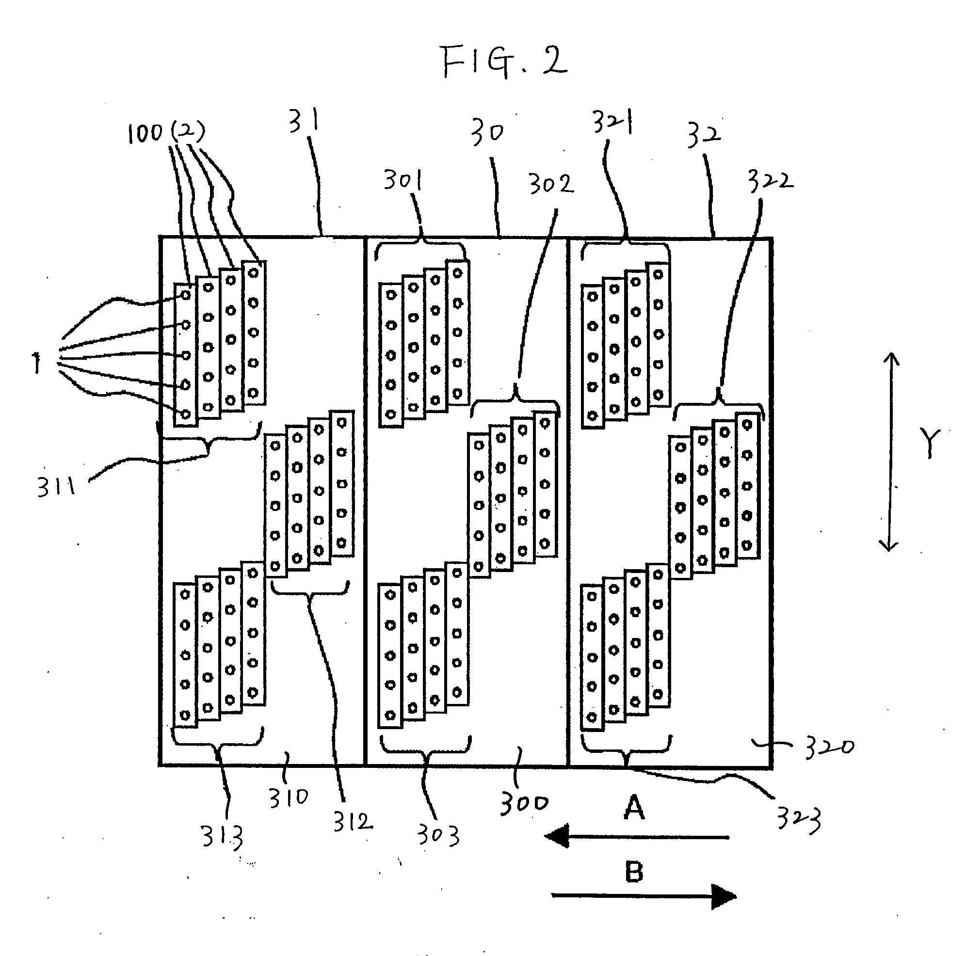
A three-dimensional laminating molding device includes ejection heads that eject support material for a support, and an ejection head that ejects mold material for a mold. The support material is sold at room temperature. An inner temperature of the laminating molding device during the laminating molding is controlled to a range of (a melting point of the support material-30)° C. to (the melting point of the support material-5)° C.

Description

[0001] 1. Field of the Invention[0002] The present invention relates to a three-dimensional laminating molding device that forms three-dimensional objects using an inkjet system.[0003] 2. Related Art[0004] A principle of a laminating molding is the same as that of a method for forming a three-dimensional contour map. That is, a three-dimensional object is sliced to produce sliced shapes, and then the sliced shapes are molded and laminated one on the other.[0005] Examples of laminating molding methods include stereolithography using a photo-curing resin, powder lamination using metallic or resin powders, melt deposition in which resin is melted and deposited, and sheet lamination in which paper sheets, plastic sheets, or thin metal plates are laminated.[0006] These laminating molding methods have spread rapidly along with a recent spread of a three-dimensional CAD and are also called rapid prototyping techniques. In these laminating molding methods, a three-dimensional object can be ...

Claims


Application Information

Patent Timeline
IPC IPC(8): B29C35/08B29C41/02B29C41/36B29C41/46B29C41/52B29C67/00B41J2/01B41M5/00
CPCB29C41/36B29C41/46B29C41/52B29K2995/002B29C67/0092B29K2105/0032B29C67/0059B33Y30/00B29C64/112B29C64/194B29C64/40B28B17/00B33Y50/02
Inventor MAEKAWA, TSUTOMUOUCHI, AKEMIFUJII, HIDETOSHITAMAHASHI, KUNIHIROSHOJI, YUTAKATAKAHAGI, HIROSHI
Owner RICOH PRINTING SYST
Learn More