Laundry machine
a technology for washing machines and washing machines, applied in washing machines, washing machines, transmission systems, etc., can solve the problems of fixed mains-frequency pump motors, low starting torque, and easy blockage of pumps, and achieve the effect of reducing the effect of ventilation
- Summary
- Abstract
- Description
- Claims
- Application Information
AI Technical Summary
Benefits of technology
Problems solved by technology
Method used
Image

Examples
first embodiment
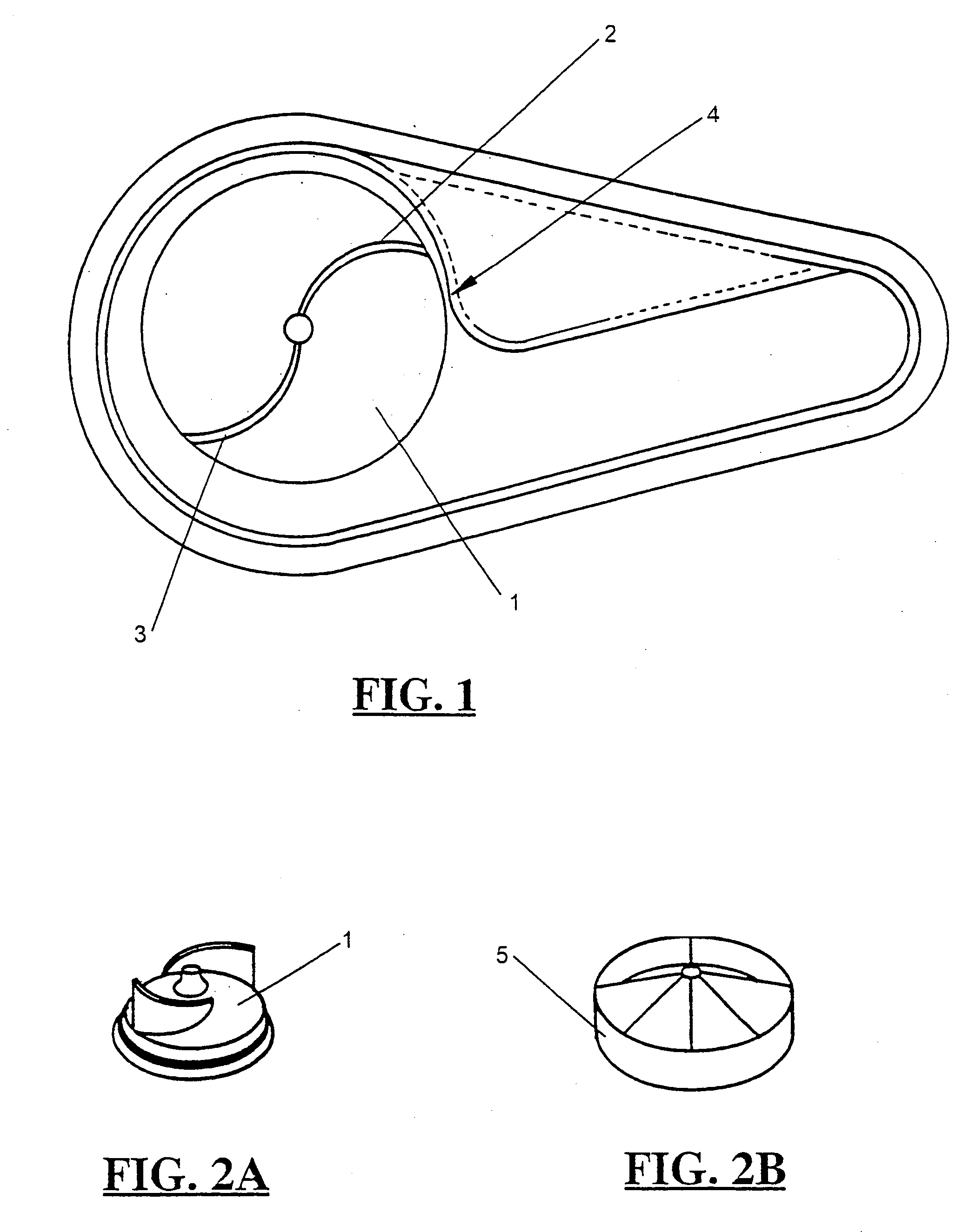
[0035] In this invention there is provided a method of drain pump motor control that will flush through bundles of fibres before they become large enough to jam the pump. Typically the pump motor will be an ac induction motor which may be of the shaded pole type. FIG. 1 shows the plan view of a laundry machine sludge pump, with the impeller 1 having two, backwardly inclined vanes 2, 3, with large clearances, especially to the cutwater 4. FIG. 2a shows a perspective view of sludge impeller 1. An alternative vortex impeller 5 (FIG. 2b) may be used to reduce pump noise. It has vane recessed into the impeller.
[0036] The method of operation involves stopping the pump very quickly for a short period of time every few seconds. The sudden stop of the pump means that there is no more energy put into the vortex, and the momentum of the water flowing down the discharge pipe sucks the vortex and any fibres entrapped in the vortex out the pump exit. The pump is started again before the velocity ...
third embodiment
[0055] In a third embodiment the invention provides a means of allowing a laundry machine power supply to power down automatically and power up via a low voltage, low current switch. This eliminates the need for a high current and / or voltage rated switch and ensures negligible power consumption when the laundry machine is not in use.
[0056] Referring to FIG. 4 power supply for the machine is produced by employing a simple switch mode power supply (SMPS) topology that is controlled by a microprocessor 17 and makes use of the main motor windings 15 and motor drive circuit 11 to 14. This general form of laundry machine power supply is described in the applicant's Australian Patent 651408. The power supply is disabled by a hardware circuit (fourth wire circuit). Power down functions are initiated by the micro processor and locked by the fourth wire circuit. Power up functions are initiated by the user via a low voltage, low current push button SWI.
Power Down
[0057] When the machine has fi...
fourth embodiment
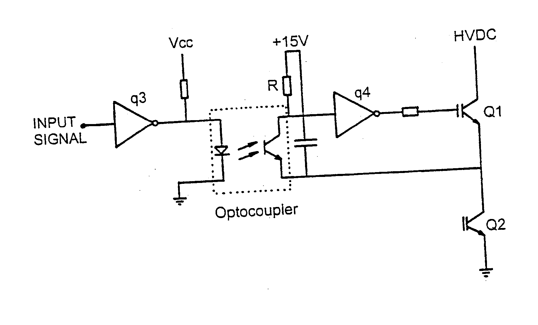
[0064] In a fourth embodiment the present invention provides a low cost high side drive for an H bridge switching circuit for an electronically commutated motor. Such a switching circuit is shown in FIG. 5 for commutating a three winding motor.
[0065] The present invention provides a more cost effective circuit to that shown in FIG. 6. This is shown in FIG. 7. Here, turn off of Q2 tends to turn on Q1. The value of resistor R is selected to limit the turn on speed of Q1 so there is no risk of overlap. Because this causes a slewed turn on for Q1, this circuit is only appropriate for switching Q1 at low frequency. Therefore the motor must be energised at audible switching frequencies.
[0066] The optocoupler can have relatively low gain and slew rate, which allows the use of a more cost effective device. There is also no need for an inverter such as q4 in FIG. 6.
[0067] Configuring at least one high side drive as in FIG. 7 is necessary to facilitate the power supply ON-OFF concept describe...
PUM
 Abstract
Description
Claims
Application Information
 - R&D
- Intellectual Property
- Life Sciences
- Materials
- Tech Scout
- Unparalleled Data Quality
- Higher Quality Content
- 60% Fewer Hallucinations
Browse by: Latest US Patents, China's latest patents, Technical Efficacy Thesaurus, Application Domain, Technology Topic, Popular Technical Reports.
© 2025 PatSnap. All rights reserved.Legal|Privacy policy|Modern Slavery Act Transparency Statement|Sitemap|About US| Contact US: help@patsnap.com