Ventilation device
A technology of ventilation device and ventilation rate, which is applied in the direction of climate sustainability, control input involving air characteristics, ventilation system, etc. question
- Summary
- Abstract
- Description
- Claims
- Application Information
AI Technical Summary
Problems solved by technology
Method used
Image

Examples
Embodiment approach
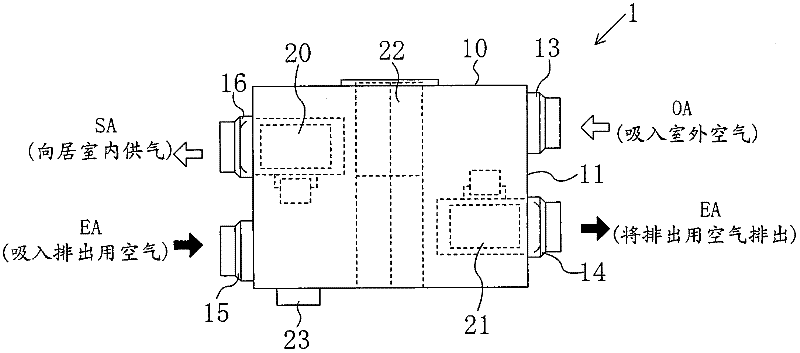
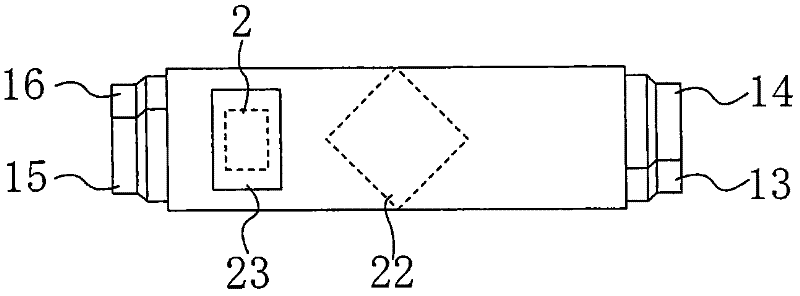
[0058] As shown in FIGS. 1 and 2 , the ventilator 1 according to the present embodiment is a ceiling-embedded duct type total heat exchanger unit. In addition, unless otherwise specified, the words "right", "left", "upper", "lower", "near" and "far" used in the following descriptions all refer to the state shown in Figure 1 .
[0059] As shown in FIG. 1 , this total heat exchanger unit 1 has a horizontally long and flat rectangular parallelepiped casing 10 . On the right side plate 11 of the housing 10, an outdoor air suction duct connection portion 13 and an exhaust duct connection portion 14 are provided. On the right side plate 11, the outdoor air suction duct connection part 13 is provided on the far side, and the exhaust duct connection part 14 is provided on the near side.
[0060] On the other hand, on the left side plate 12 of the housing 10, an indoor air suction duct connection portion 15 and an air supply duct connection portion 16 are provided. On the left side ...
example 2—
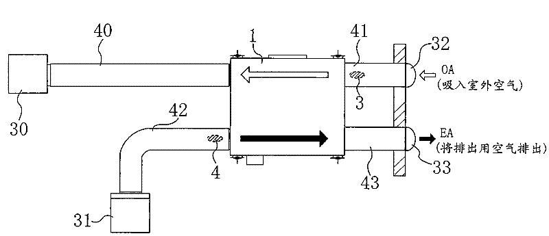
[0102] Modification 2 of the embodiment differs from this embodiment in that in the modification 2 of the embodiment, the total heat exchanger unit 1 is connected to the air conditioners 5 and 6 which are the cooling mechanism and the heating mechanism installed in the living room. Linkage, while running.
[0103] Figure 4 The illustrated air conditioners 5 and 6 are configured to be capable of switching between cooling operation and heating operation. In the living room, an air conditioner remote control 7 for the user to operate the air conditioners 5 and 6 is installed. The air conditioner remote controller 7 is connected to an air conditioner control board 8 for controlling the operation of the air conditioners 5 and 6 via electrical wiring. Furthermore, the air-conditioning control board 8 and the total heat exchanger unit controller 2 are connected by electrical wiring.
[0104] The air conditioner remote controller 7 outputs an operation signal for starting or stopp...
other Embodiment approach
[0114] The above-described embodiments may also take the following configurations.
[0115] In the present embodiment, the ventilator constitutes a ceiling-embedded duct type total heat exchanger unit 1 . The ventilation device of the present invention is not limited to the total heat exchanger unit 1 described above, and may be, for example, a ceiling-embedded box-type total heat exchanger unit. In addition, the box-type total heat exchanger unit is provided with an air outlet and an air inlet on the bottom surface of the casing 10 . In this case, the living room can be ventilated without providing the air supply grill 30 and the exhaust grill 31 .
[0116] Also, in this embodiment, the air supply fan 20 and the exhaust fan 21 are operated intermittently at the same time. The present invention is not limited thereto, and the two fans 20, 21 may also be operated separately. In this case, if the air supply fan 20 is driven for a long time, a positive pressure can be formed i...
PUM
 Abstract
Description
Claims
Application Information
 - Generate Ideas
- Intellectual Property
- Life Sciences
- Materials
- Tech Scout
- Unparalleled Data Quality
- Higher Quality Content
- 60% Fewer Hallucinations
Browse by: Latest US Patents, China's latest patents, Technical Efficacy Thesaurus, Application Domain, Technology Topic, Popular Technical Reports.
© 2025 PatSnap. All rights reserved.Legal|Privacy policy|Modern Slavery Act Transparency Statement|Sitemap|About US| Contact US: help@patsnap.com