
Electrochemical fuel cell comprised of a series of conductive compression gaskets and method of manufacture

a technology of conductive compression gaskets and fuel cells, which is applied in the direction of cell components, final product manufacturing, sustainable manufacturing/processing, etc., can solve the problems of obstructing commercial development and deployment, technical and economic difficulties, and abating the realization of pem fuel cell technology as a viable commercial means, so as to facilitate mass-production and low-cost fuel cell products

Inactive Publication Date: 2004-01-29
TETROS INNOVATIONS LLC
View PDF20 Cites 43 Cited by
  • Summary
  • Abstract
  • Description
  • Claims
  • Application Information

AI Technical Summary

Benefits of technology

[0014] Moreover, the present invention includes manufacturing methods that facilitate mass-production and low-cost fuel cell products. Rather than employing conventional methods of manufacturing fuel cell separators, such as machining and sintering, the conductive compression gaskets that comprise the fuel cell separators of the present invention can be formed by cutting, punching, stamping, etc. It should also be noted that the present invention is relevant to other similar apparatus that would benefit from the utility of the present invention, such as other classes of chemical and electrochemical energy converters, such as electrolysis cells.BRIEF DESCRIPTION OF THE SEVERAL VIEWS OF THE DRAWINGS

Problems solved by technology

Yet, heretofore, technical and economical difficulties have abated the realization of PEM fuel cell technology as a viable commercial means for producing energy.
Both the technical and economical difficulties originate from material issues concerning the materials employed within PEM fuel cell embodiments.
One of the most considerable material issues obstructing the commercial development and deployment of PEM fuel cells originates with the materials comprising the separators.
Ordinary metallic separators, fabricated from aluminum for example, will corrode and produce minute metal particulate that will react with the electrocatalyst and terminally diminish or arrest the electrochemical reactions.
While the use of gold-plated, alloy-plated or exotic separators can prevent electrocatalyst poisoning, it is not cost effective for the large-scale commercial market.
Graphite separators are more cost effective than metallic separators because they are made from a less expensive material, and they are more chemically compatible with the electrochemical reaction but they present several technical complications concerning material integrity.
Machining graphite separators often requires tortuous tooling paths and complicated construction geometries that make the separators susceptible to technical problems during operation, such as crossover and overboard leakage, incongruous components and compromised structural integrity, etc.
The loose graphite material is formed into a separator under thermal compression; this operation is susceptible to non-uniform compression and thermal gradation, which can translate into material imperfections and structural integrity problems, such as internal voids, surface defects and cracking.
In addition, both machining and sintering are relatively expensive manufacturing methods and require long part-fabrication times. Moreover, graphite separators inherently exhibit lower thermal and electrical conductivity than metallic separators, thereby limiting the potential electrical generation of the fuel cell.
From a technical perspective, a significant shortcoming in the development of PEM fuel cells for commercial production is the inability to prevent reactant leakage between fuel cell components.
The interfaces between the fuel cell components are susceptible to reactant leakage because the complementary surfaces are not completely mutually conformable.
Crossover leaks (from one internal fluid stream to another) and overboard leaks (from interior fluid streams to the exterior environment) inhibit the performance, efficiency, power density, stoichiometry, etc. of the fuel cell system.
However, the employment of gaskets within the fuel cell is a qualified solution because it also complicates several issues, such as the fuel cell design, construction, material compatibility and product life expectancy.
Moreover, fuel cell embodiments that employ graphite separators typically incorporate non-active cooling cells intermittently within the fuel cell stack rather than within individual fuel cells.
This type of PEMFC construction is susceptible to thermal gradients, which are detrimental to the performance of the fuel cell stack and exacerbates water managements issues of dehydration and flooding.

Method used


Image

  • Electrochemical fuel cell comprised of a series of conductive compression gaskets and method of manufacture
  • Electrochemical fuel cell comprised of a series of conductive compression gaskets and method of manufacture
  • Electrochemical fuel cell comprised of a series of conductive compression gaskets and method of manufacture

Examples


Embodiment Construction

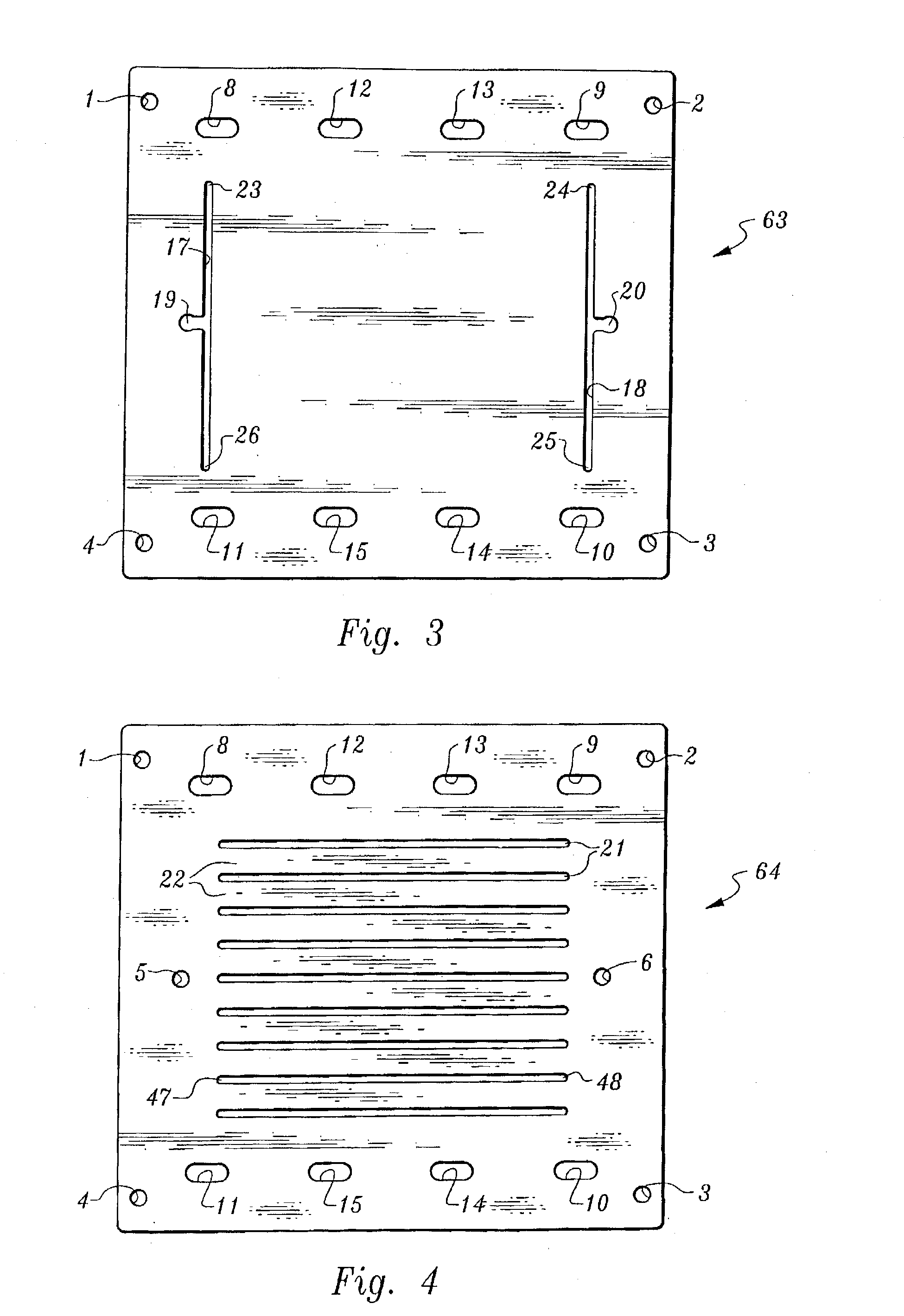
[0024] To understand the disclosure of the various embodiments and modifications of embodiments that follows, a detailed explanation of the Figures and their respective components is helpful:

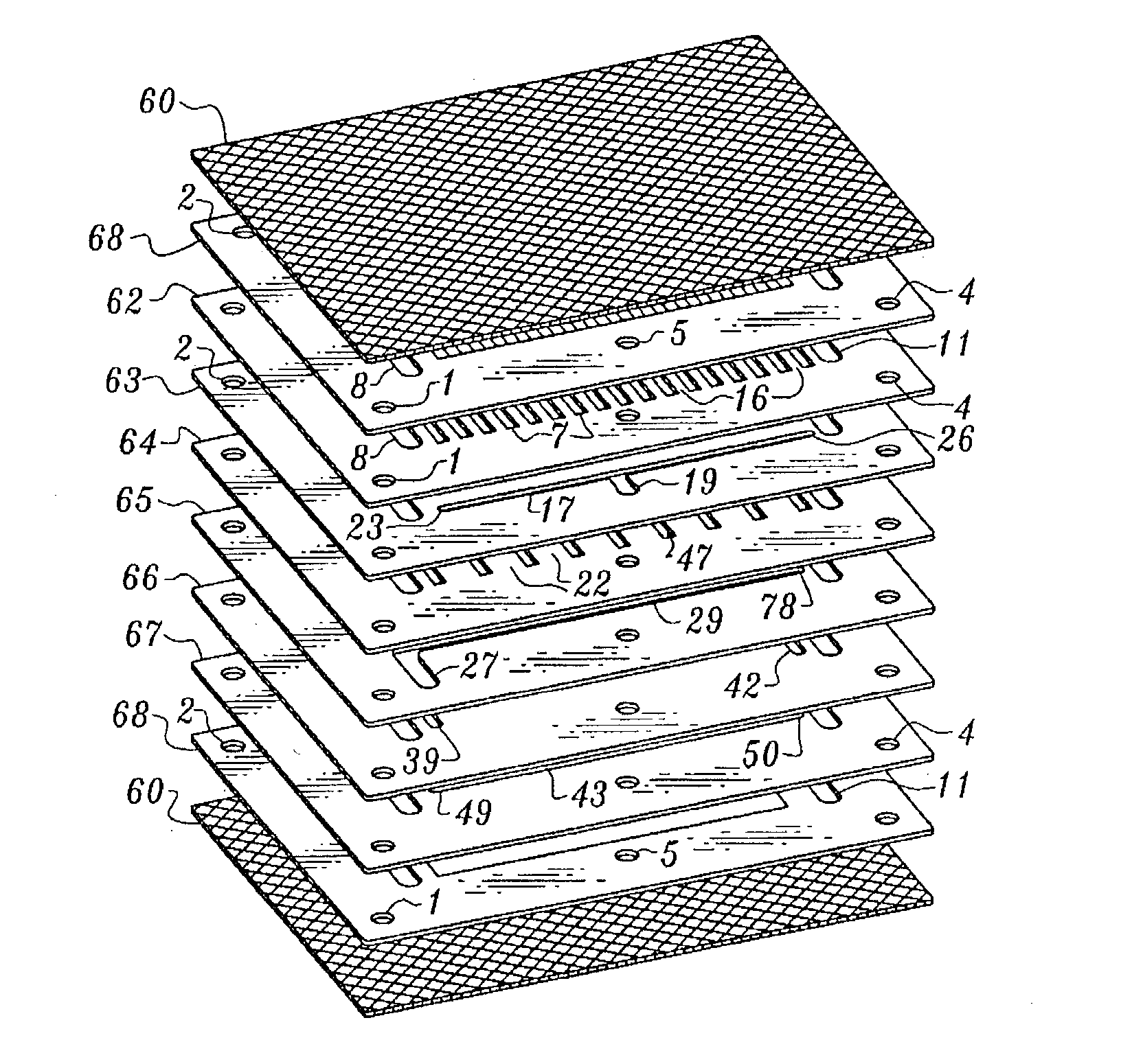
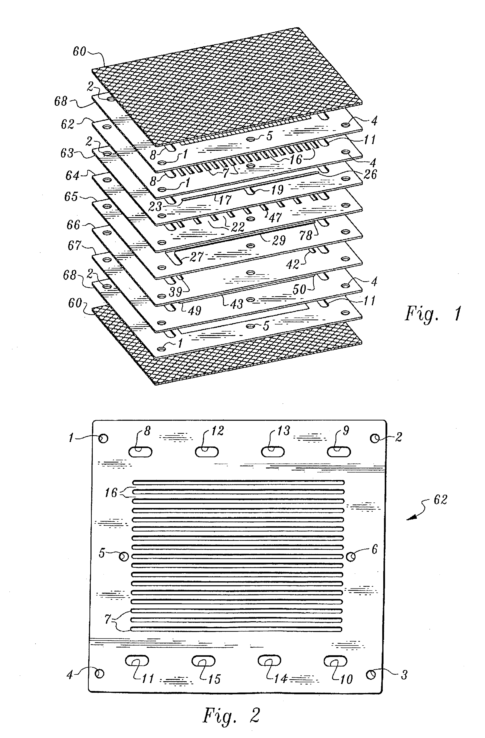
[0025] FIG. 1 shows the exploded isometric view of a consolidated bipolar separator that embodies an example of the disclosed invention, the various components which make up this view are:

[0026] The chemically benign meshes 60 are intended to interface with the MEA, which is not shown. The mesh is open enough, to allow the reactants to flow and diffuse from the channel features 7 and 43 to their respective electrodes within the MEA.

[0027] The chemically benign structural frame 68 comprising die-stamped through-features that allow the fuel cell fluids--fuel, oxidant and HTF--to pass through the structural frame. These features are the fuel manifold inlet 5; HTF manifolds, 8, and 11; and the oxidant manifold mediate inlet ducts 33 and 34 (see FIG. 6). Likewise, the structural frames circumscribe t...


PUM

PropertyMeasurementUnit
Electrical conductivityaaaaaaaaaa
Flow rateaaaaaaaaaa
Flexibilityaaaaaaaaaa

Abstract

A novel electrochemical fuel cell comprising at least one fuel cell assembly comprising a Membrane Electrode Assembly (MEA) interposed between an anode separator and a cathode separator. The Membrane Electrode Assembly comprises a solid polymer electrolyte or Proton Exchange Membrane (PEM) interposed between an anode and a cathode, each electrode comprising electrocatalyst. The anode separator contains the fuel flow field distribution features necessary to communicate the fuel to said anode. The cathode separator contains the oxidant flow field distribution features necessary to communicate the oxidant to said cathode. In addition, a Heat Transfer (HT) separator may be integrated into said fuel cell assembly. The Heat Transfer separator contains the flow field distribution features necessary to communicate Heat Transfer Fluid (HTF) through a Heat Transfer Zone (HTZ) in said fuel cell assembly in order to control the thermal conditions of the fuel cell assembly and stack. Each of the said anode, cathode and Heat Transfer separators are made up of a respective series of multiple conductive compression gaskets possessing inter-related fluid distribution channel and manifold features that form intra-communicating systems for the distribution of fuel, oxidant and Heat Transfer Fluid throughout the fuel cell separator and stack. Under sufficient mechanical load, the respective series of multiple compression gaskets are consolidated into fuel cell separators that demonstrate sufficient structural integrity to contain the PEMFC fluids under substantial pressure; that demonstrate sufficient electrical and thermal conductivity to enable the operation of a high-performing Proton Exchange Membrane Fuel Cell; that demonstrate sufficient material obduracy to bear the compressive load necessary to seal the fuel cell assembly and fuel cell stack; and that demonstrate sufficient fluid impermeability in order prevent fluid migration through the gasket material. Within the consolidated fuel cell separators, the inter-related channel and manifold features form an intra-communicating system for the distribution of fuel, oxidant and Heat Transfer Fluid throughout the fuel cell assembly and fuel cell stack. In addition, the present invention includes methods of manufacturing said electrochemical fuel cell.

Description

[0001] This application claims the benefit of U.S. Provisional Application No. 60 / 379,523, filed on May 9, 2002.[0002] 1. Field of the Invention[0003] The present invention relates to electrochemical energy converters such as fuel cells or electrolysis cells. More particularly, it relates to Proton Exchange Membrane Fuel Cells (PEMFCs). The present fuel cell invention can be categorized further as relating to PEMFCs constructed, in part, of separators, each comprised of a respective series of conductive compression gaskets possessing inter-related fluid distribution channel and manifold features.[0004] 2. Description of the Prior Art[0005] The class of electrochemical fuel cells comprising Proton Exchange Membranes (PEMs) convert the chemical energy of a hydrogen fuel and an oxidant into electrical energy, heat and water. Generically, PEM fuel cells employ Membrane Electrode Assemblies (MEAs) comprising a solid polymer electrolyte or ionomeric membrane interposed between an anode an...

Claims


Application Information

Patent Timeline
IPC IPC(8): H01M8/02H01M8/04H01M8/10H01M8/24
CPCH01M8/0258H01M8/0267H01M8/0273Y02E60/50H01M8/0284H01M8/242H01M8/028H01M8/2483Y02P70/50
Inventor ORSBON, WYATT B.HODGE, REX A.BECKER, ROLF R.
Owner TETROS INNOVATIONS LLC
Learn More