
Method of manufacturing an enamel having a low coefficient of friction, and an electrical conductor coated in such an enamel

Inactive Publication Date: 2003-11-20
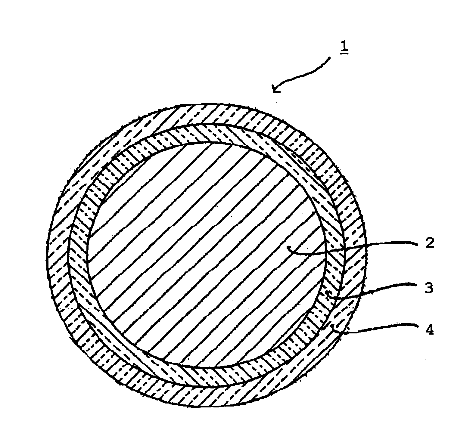
ESSEX EURO
View PDF3 Cites 12 Cited by
  • Summary
  • Abstract
  • Description
  • Claims
  • Application Information

AI Technical Summary

Benefits of technology

[0014] The object of the present invention is thus to develop a method of manufacturing an enamel of the above-mentioned type that does not lead to anticipated deterioration of the polymerizing oven and that enables an enamel to be made which is stable over time and which has improved sliding properties, i.e. a coefficient of friction which is lower than that of prior art enamels.
[0018] Thus, by means of the invention, the polysiloxane is subjected to pre-processing so as to incorporate one or more organic (hydrocarbon) chains identical to those of the enamel that is to be synthesized. As a result, during synthesis of the enamel, the grafted polysiloxane reacts in full, and no residue remains that could be harmful to the polymerizing oven. Furthermore, the grafted polysiloxane dissolves better in the organic medium so the resulting final enamel is more stable than in the prior art. In addition, the coefficient of friction of the enamel is considerably smaller than that of prior art enamels.
[0022] This serves to further improve the sliding properties of the enamel by increasing the silicone content of the enamel.

Problems solved by technology

These wires are produced at very high speeds, and they are therefore subjected to high levels of mechanical stress and friction which can damage their insulation and can lead to irregular winding.
Inserting coils also leads to the same type of stresses and friction.
That method is not satisfactory.
This gives rise in particular to damage to the catalyst in the polymerizing oven, and causes it to degrade early.
In addition, the resulting enamel is not stable over time, and after a few hours the enamel is observed to segregate, with a solid deposit forming on the surface of the liquid.
The enamel obtained in that way is also unstable, i.e. it precipitates.
In addition, it does not possess a coefficient of friction that is as low as desired.

Method used


Image

  • Method of manufacturing an enamel having a low coefficient of friction, and an electrical conductor coated in such an enamel

Examples


example 1

[0028] In this example, the grafted polysiloxane is for use in synthesizing polyamide-imide.

[0029] 0.15 moles of acid functionalized polysiloxane and 1.5 moles of diphenylmethane di-isocyanate (MDI) constituting the first functionalized monomer are introduced into 1000 grams (g) of N-methylpyrolidone at 80.degree. C.

[0030] The mixture is heated to 190.degree. C. and stirred at said temperature for 2 hours. This produces a functionalized polysiloxane oligomer, i.e. comprising isocyanate functional groups.

[0031] The solution is then cooled to 120.degree. C. and 1.2 moles of trimellitic anhydride (TMA) are added at the second functionalized monomer. The mixture is heated to 160.degree. C. for 2 hours. A polysiloxane is obtained that is grafted with short organic chains identical to those of the final polyamide-imide enamel.

[0032] 0.3 moles of polysiloxane are then reacted by heating the mixture to 190.degree. C. and then stirring the mixture at said temperature for 1 hour.

[0033] The re...

example 2

[0034] In this example, the grafted polysiloxane is for use in the synthesis of the polyamide.

[0035] 0.15 moles of acid functionalized polysiloxane and 1.5 moles of MDI as the first functionalized monomer are added into 1000 g of N-methylpyrrolidone at 80.degree. C.

[0036] The mixture is heated to 190.degree. and stirred at said temperature for 2 hours. A functionalized polysiloxane oligomer is obtained, i.e. comprising isocyanate functional groups.

[0037] The solution is then cooled to 120.degree. C. and 1.2 moles of terephthalic acid (TPA) as the second functionalized monomer are added. The mixture is heated to 160.degree. C. for 2 hours and stirred at said temperature for 1 hour. This produces a polysiloxane grafted with short organic chains identical to those of the final polyamide enamel.

[0038] 0.3 moles of polysiloxane are then caused to react by heating the mixture to 190.degree. C., and the mixture is then stirred at said temperature for 1 hour.

[0039] The resulting diacid is t...

example 3

[0040] In this example, the grafted polysiloxane is for use in synthesizing polyester or polyester-imide.

[0041] 0.15 moles of acid functionalized polysiloxane and 1.5 moles of methyl ethyl glycol as the first functionalized monomer are added into 1000 g of cresol. A functionalized polysiloxane oligomer is obtained, i.e. comprising alcohol functional groups.

[0042] After the reaction, 1.2 moles of terephthalic acid (TPA) as the second functionalized monomer are added to the solution. The mixture is allowed to react to form an alcohol-grafted polysiloxane with short organic chains identical to those of the final polyester or polyester-imide enamel.

[0043] 0.3 moles of polysiloxane are then caused to react.

[0044] The diacid formed in this way is then introduced into the synthesis of the polyester or polyester-imide that is involved in synthesizing polyurethanes, replacing a varying fraction of the usual diacids.

[0045] Here again the synthesis is entirely conventional and well known to th...


PUM


Abstract

The present invention relates to a method of manufacturing enamels selected from: polyurethanes, polyamides, polyamide-imides, polyesters, polyester-imides, polyester amide-imides, polyimides, polyepoxy compounds, and polyphenyl oxide compounds; said method comprising an operation in which a functionalized polysiloxane oligomer is obtained by causing a functionalized polysiloxane having a reactive first functional group to react with a first functionalized monomer used in synthesizing said enamel, said first monomer having a second functionalized group that reacts with said first functional group. According to the invention, the method subsequently comprises the following operations: said functionalized polysiloxane oligomer is caused to react with a second functionalized monomer that is used in synthesizing said enamel, said second monomer having a third functional group that reacts with said functionalized polysiloxane oligomer, thereby obtaining a grafted polysiloxane having organic chains that are identical to those of said enamel; and said enamel is synthesized using said first and second monomers and said grafted polysiloxane.

Description

[0001] The present invention relates to a method of manufacturing a magnet wire enamel having a low coefficient of friction, and to an electrical conductor coated in such an enamel.[0002] In the manufacture of electric motors, the larger the quantity of winding wire that can be incorporated in the core of the stator, the better the performance of the motor. In addition, motor manufacturers also seek to increase manufacturing yield. Thus, in known manner, coils are inserted into stators automatically.[0003] The wires used in such electric motors are typically constituted by an electrical conductor coated in one or more insulating layers based on enamel.[0004] These wires are produced at very high speeds, and they are therefore subjected to high levels of mechanical stress and friction which can damage their insulation and can lead to irregular winding. Inserting coils also leads to the same type of stresses and friction.[0005] To solve that problem, document U.S. Pat. No. 4,693,936 d...

Claims


Application Information

Patent Timeline
IPC IPC(8): C08G63/83C08G18/34C08G73/10C08G77/42C08G77/452C09D5/25C09D163/00C09D167/00C09D175/04C09D177/00C09D179/08C09D183/04C09D183/10C09D201/00H01B3/46H01B7/02
CPCC08G77/42H01B3/46C09D183/10C08G77/452Y10T428/31663
Inventor STUDER, VIRGINIEPIECHAZYK, ARNAUDSCHILDKNECHT, LAURENT
Owner ESSEX EURO
Learn More