
Carbon fiber electrode substrate for electrochemical cells

a technology of electrochemical cells and electrode substrates, which is applied in the direction of fuel cell details, final product manufacturing, synthetic resin layered products, etc., can solve the problems of high impregnated substrates, low ohmic (electrical) resistance and adequate mechanical strength, and high resistance in the through-plane direction, etc., to achieve high electrical conductivity, high carbon content, and high porosity

Active Publication Date: 2003-10-16
SGL CARBON SE
View PDF11 Cites 47 Cited by
  • Summary
  • Abstract
  • Description
  • Claims
  • Application Information

AI Technical Summary

Benefits of technology

[0016] To achieve the above targets, it is an object the invention to provide an electrode substrate that combines the preferable features of the commercially available state-of-the-art carbon fiber sheet electrode substrates, i.e. high carbon content (a mass fraction in excess of 98%) and therefore high electrical conductivity with the advantage of high porosity and continuous processability as rolled good.
[0017] It is another object of the invention to provide a method for the manufacturing of an electrode substrate according to the invention from a low cost precursor.

Problems solved by technology

On the other hand, the requirements of low Ohmic (electrical) resistance and adequate mechanical strength have to be fulfilled, too.
The carbonized binder particles contribute not only to the mechanical stability of the ES but also bring about a lowering of the resistivity in the through-plane direction which otherwise would be poor because of the mainly planar alignment of the carbon fibers within the mat.
Such highly-impregnated substrates suffer from two major disadvantages: low porosity (less than 80%) which is detrimental to reactant transport, and poor flexibility.
Therefore, further processing of the electrode substrate has to be carried out batch-wise resulting in high process costs and large inter-lot variations due to the difficult control of the batch-wise processing steps.
This temperature range is sufficient for sintering of fluoro resins like PTFE and thermosetting of phenolic or epoxy resins, but not for carbonization of a resin.
Thus an electrode substrate made of such fibers probably will not match price targets for fuel cell commercialization.

Method used


Image

  • Carbon fiber electrode substrate for electrochemical cells
  • Carbon fiber electrode substrate for electrochemical cells
  • Carbon fiber electrode substrate for electrochemical cells

Examples


example 1

[0094] A carbon fiber paper characterized by a porosity of approximately 95%, a through-plane resistance of 60 mOhm.multidot.cm.sup.2 and a thickness of 0.17 mm was used as the precursor. The carbon fiber paper was made of PAN-based carbon fibers with a diameter of 7 .mu.m available under the trademark .RTM.SIGRAFIL C. The paper was utilized as rolled good.

[0095] The paper web was two times impregnated with a water-based slurry containing mass fractions of 10% of dispersed phenolic resin and 10% of graphite powder, with 90% of the particles being smaller than 5.5 .mu.m. The impregnated paper was dried and the resin was cured. For drying and curing the paper webs were conveyed at a rate of 100 m / h through a continuous furnace. The temperature the material was subjected to increased from 100.degree. C. at the entrance zone of the furnace to 250.degree. C. near the exit. Subsequently the resin impregnated paper was graphitized under a nitrogen atmosphere at a temperature of 1700.degree...

example 2

[0096] A carbon fiber paper made of PAN based carbon fibers (.RTM.SIGRAFIL C, 7 .mu.m diameter), characterized by a porosity of approximately 94%, through-plane resistance of 60 mOhm.multidot.cm.sup.2 and a thickness of 0.28 mm was used as the precursor. Further processing was the same as in Example 1

example 3

[0097] The precursor of Example 2 was impregnated once only and further processed as described in Example 1.


PUM

PropertyMeasurementUnit
thicknessaaaaaaaaaa
thicknessaaaaaaaaaa
mean lengthaaaaaaaaaa

Abstract

This invention relates to electrode substrates for electrochemical cells, particularly low-temperature fuel cells, and processes for their production. Low-cost carbon fiber paper structures are used as precursor for preparation of an all-carbon product that has a high electric conductivity and porosity and can be processed in a continuous reel-to-reel mode. These paper materials are further impregnated and processed to adjust the final product properties. This all-carbon electrode substrate is not brittle thereby avoiding the main disadvantage of the prior art.

Description

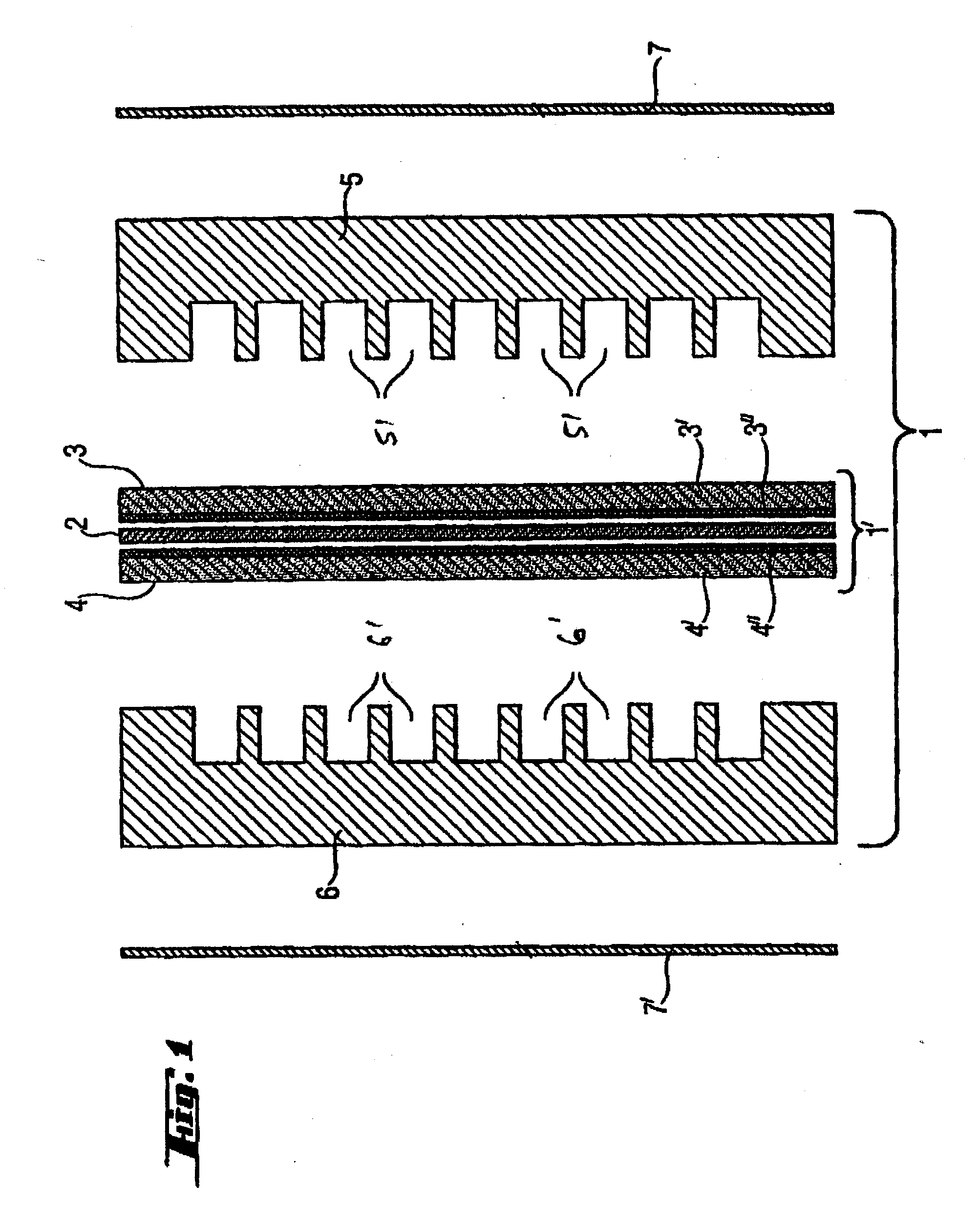
CLAIM FOR PRIORITY[0001] This non-provisional application claims the benefit of the filing date of U.S. Provisional Patent Application No. 60 / 372,538, of the same title, filed Apr. 12, 2002.[0002] The invention relates to electrode substrates for electrochemical cells, particularly Polymer Electrolyte Membrane Fuel Cells (PEMFC) and Phosphoric Acid Fuel Cells (PAFC), and processes for their production.[0003] A fuel cell converts a fuel such as hydrogen, and an oxidant, typically oxygen or air, via electrochemical reactions into electricity, reaction products and excess heat. As shown in FIG. 1, a single fuel cell 1 is typically constituted of an electrolyte layer e.g. a proton-conducting polymer membrane 2, sandwiched between two typically flat porous electrodes 3 and 4, individually referred to as the anode and the cathode. The electrodes 3 and 4 are comprised of reactant-permeable electron-conducting substrates 3' and 4' with the surfaces adjacent to the electrolyte covered with t...

Claims


Application Information

Patent Timeline
Patent Type & Authority Applications(United States)
IPC IPC(8): H01M4/96D21H13/50H01M4/86H01M4/88H01M8/02H01M8/10H01M8/24
CPCD21H13/50H01M4/8605H01M4/8807Y10T428/30H01M8/0234H01M8/0243Y02E60/50H01M4/881C04B35/6269C04B35/63436C04B35/65C04B35/83C04B2235/425C04B2235/5248C04B2235/5252C04B2235/5264C04B2235/5436C04B2235/606C04B2235/616C04B38/0032C04B2111/00844Y10T428/249945Y02P70/50C04B38/0054C04B38/0074
Inventor WILDE, PETERMAENDLE, MICHAELLEINFELDER, HEIKOSTEINHART, JOSEF
Owner SGL CARBON SE
Learn More