Image forming apparatus
- Summary
- Abstract
- Description
- Claims
- Application Information
AI Technical Summary
Benefits of technology
Problems solved by technology
Method used
Image
Examples
embodiment 1
[0086] Embodiment 1
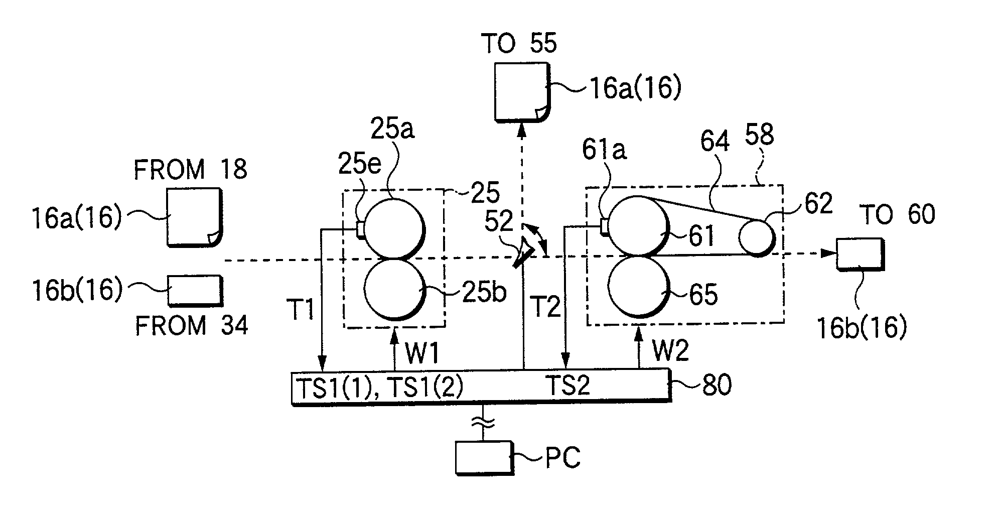
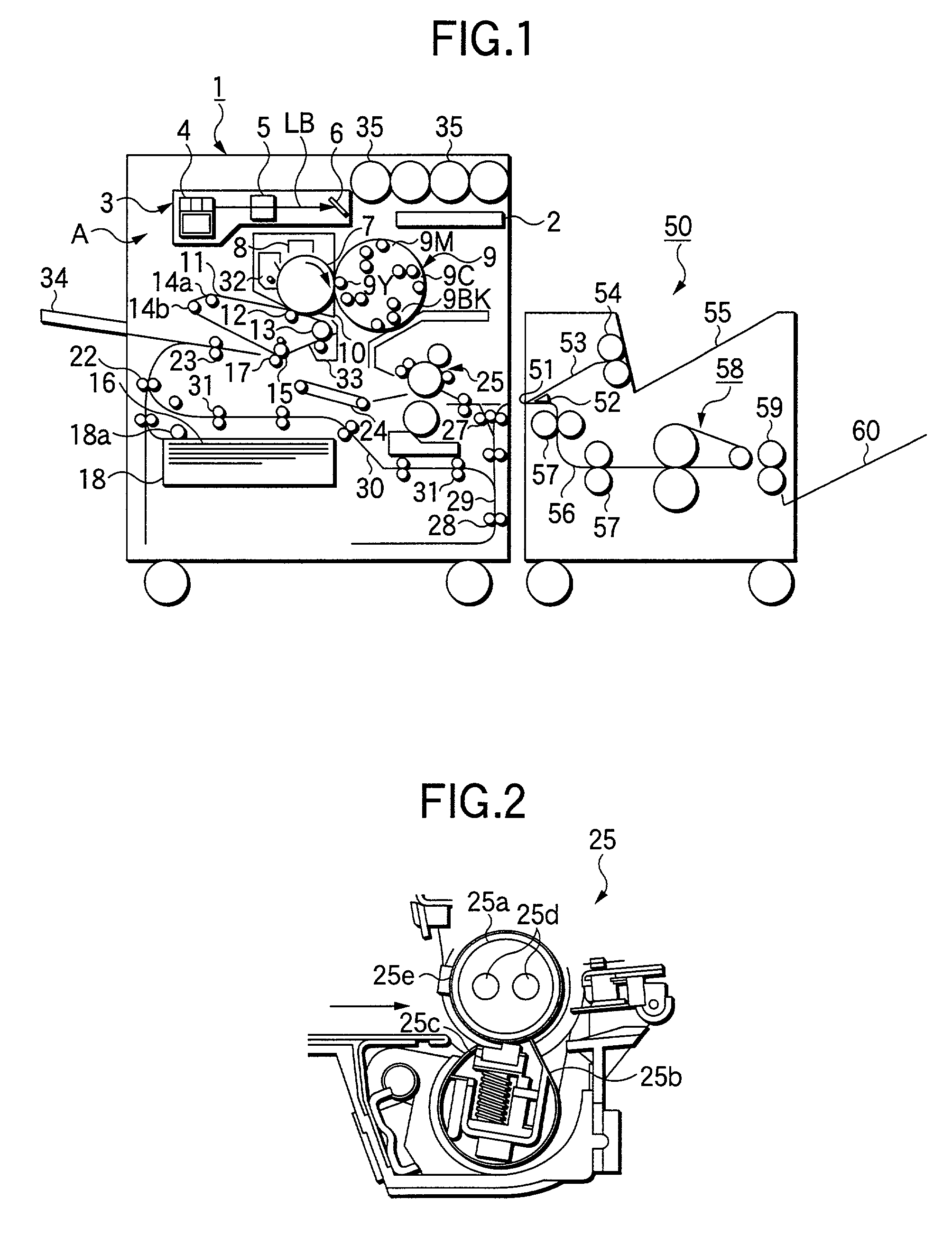
[0087] A first measure to reduce the power consumption, which is employed in the embodiment, is to reduce the size of the second fixing device 58, in particular, the belt width of the fixing belt 64.
[0088] The second fixing device 58 in the embodiment repeats such a cycle that the recording sheet 16 (including the dedicated glossy paper 16b), together with the fixing belt 64, is heated and cooled. Accordingly, in general, the power consumption by the second fixing device is considerably large.
[0089] FIG. 7 is a graph explaining a relationship between the power consumption of the second fixing device 58 when it is idle (8 ppm) and the fixing belt 64. The power consumption of four kinds of the second fixing devices 58 of which the fixing belts 64 are different in width when those are in idle are measured (Those fixing belts were 130, 180, 240, and 330 mm in width.). The measured power consumption for the belt widths are plotted on the, graph, and the plotted points ...
embodiment 2
[0111] Embodiment 2
[0112] An embodiment 2 of the invention will be described.
[0113] In the embodiment, in addition to the total power of 1,750 W in the embodiment 1, the following electric power is consumed: 200W of a halogen lamp 69a (in addition to the halogen lamps 69 of 650 W) added to the fuser roll 61 of the second fixing device 58, and 200 W of a halogen lamp 69b added to the pressure roll 65. The fuser roll 25a (650W) of the first fixing device 25 and the halogen lamp 69 (650 W) of the second fixing device 58 are controlled so as not to be turned on simultaneously. The halogen lamp 69a (200 W) of the fuser roll 61 and the halogen lamp 69b (200 W) of the pressure roll 65, are also controlled so as not to be turned on simultaneously.
[0114] Table 6 tabulates a temperature control logic in this case. Table 7 tabulates the total power consumption of the embodiments 1 and 2.
6 TABLE 6 Temperature of first fixing device Temperature of first fixing device < preset temperature .gtoreq...
embodiment 3
[0118] Embodiment 3
[0119] An embodiment 3 of the invention will be described.
[0120] An image forming system of the embodiment incorporates the first to third measures for the power consumption reduction which are described in the embodiment 1, and further a fifth measure. The fifth measure, when the electric power is simultaneously supplied to both the halogen lamp 25d of the first fixing device 25 and the halogen lamp 69 of the second fixing device 58, cut-off power is supplied to the halogen lamps 25d and 69 so that the total of the supplied power is smaller in value than preset power.
[0121] FIG. 12 is a graph showing the results of measuring the output electric power while the cut-off time is varied from 10 to 190 msec, under the condition that one cycle of power source voltage of 650VA is 200 msec. The graph teaches that desired electric power may be supplied by adjusting the cut-off time.
[0122] FIG. 13 shows a time transition of the maximum power consumption of the first fixing...
PUM
 Abstract
Description
Claims
Application Information
 - R&D
- Intellectual Property
- Life Sciences
- Materials
- Tech Scout
- Unparalleled Data Quality
- Higher Quality Content
- 60% Fewer Hallucinations
Browse by: Latest US Patents, China's latest patents, Technical Efficacy Thesaurus, Application Domain, Technology Topic, Popular Technical Reports.
© 2025 PatSnap. All rights reserved.Legal|Privacy policy|Modern Slavery Act Transparency Statement|Sitemap|About US| Contact US: help@patsnap.com


