
Ceramic honeycomb filter and its structure

Inactive Publication Date: 2003-09-04
HITACHI METALS LTD
View PDF10 Cites 57 Cited by
  • Summary
  • Abstract
  • Description
  • Claims
  • Application Information

AI Technical Summary

Benefits of technology

[0016] Accordingly, an object of the present invention is to provide a ceramic honeycomb filter having small pressure loss free from cracking due to thermal stress and thermal shock at the time of regenerating the filter, and a ceramic honeycomb structure used therefor.
[0017] Another object of the present invention is to provide a ceramic honeycomb structure, in which cracking is less likely to propagate continuously in a diagonal direction of cells along partition wall intersections on which stress is concentrated.
[0018] A further object of the present invention is to provide a high-strength ceramic honeycomb structure capable of being used as a particulates-capturing filter stably for a long period of time even with porosity of 50% or more.

Problems solved by technology

Though the pressure loss can be reduced by increasing the porosity and pore size of partition walls or by decreasing exhaust gas resistance, larger porosity and pore size leads to lower strength in the partition walls, resulting in low breakage resistance of the filter.
Further, sealers formed at both ends of the honeycomb filter not only increases the pressure loss, but also lowers the thermal shock resistance.
It is thus difficult to satisfy both of the requirements of pressure loss and breakage resistance.
However, the ceramic honeycomb structure of JP 7-332064 A, as described in its Examples, has as small porosity as 45% and thus large pressure loss of a ceramic honeycomb filter.
Because it does not have pores in sealers on an inlet side while it has pores in sealers on an exit side, an exhaust gas cannot pass through the sealers on the inlet side, resulting in insufficient effect of reducing the pressure loss.
However, when the seal depth of the honeycomb filter is nonuniform, there is only a small effective area as a filter in portions having large seal depth, resulting in large pressure loss.
Also, with the nonuniform seal depth, filter areas differ from product to product, causing the problem that the resultant honeycomb filters do not have constant quality.
Further, there is weak adhesion strength between the sealers and the partition walls in portions having small seal depth, the sealers are likely to peel off by the pressure of an exhaust gas or thermal shock, etc.
Accordingly, when used for catalyst converters and particulates-capturing filters, it is likely to suffer from cracking 13 in partition wall intersections by thermal shock or stress as shown in FIG. 6, resulting in breakage in a diagonal direction of cells.
However, because the partition walls are not thick in a core portion of the ceramic honeycomb structure, the partition wall intersections have uniform strength, so that cracking generated in the partition wall intersections continuously propagate through the core portion.
However, because the strength of the partition wall intersections is uniform throughout the ceramic honeycomb structure, cracking generated by thermal shock or stress continuously propagates along the partition wall intersections.
However, because these porous ceramic honeycomb filters have high porosity, they inevitably have low strength.
Therefore, stress concentration is likely to occur in the pores, causing decrease in the strength of the ceramic honeycomb structure.
Thus, when it is used for particulates-capturing filters for exhaust gases from diesel engines, it is likely to be broken by thermal stress and shock, a mechanical fastening force at the time of assembling, vibration, etc.

Method used


Image

  • Ceramic honeycomb filter and its structure
  • Ceramic honeycomb filter and its structure
  • Ceramic honeycomb filter and its structure

Examples


reference examples 1-6

[0082] To form cordierite having a main component composition comprising 49-51% by mass of SiO.sub.2, 35-37% by mass of Al.sub.2O.sub.3 and 13-15% by mass of MgO, a cordierite-forming starting material powder comprising kaolin powder, calcined kaolin powder, alumina powder, aluminum hydroxide powder, silica powder and talc powder was mixed with a binder, a lubricant and spherical resin powder as a pore-forming material in predetermined amounts, and further fully mixed with water in a predetermined amount to form a plasticizable batch capable of being extrusion-molded to a honeycomb shape.

[0083] With the size of an extrusion die and the amount of a pore-forming material adjusted, honeycomb green bodies with square cross sections of flow paths and partition walls having various thickness and porosity were produced. Each green body was sintered after drying, to form a ceramic honeycomb structure of 150 mm in diameter and 150 mm in length. A pitch of partition walls was 1.5 mm in the re...

examples 8-13

[0107] A cordierite ceramic honeycomb filter 10 of 150 mm in outer diameter and 150 mm in length with 0.3-mm-thick partition walls at a pitch of 1.5 mm was produced in the same manner as in Example 1. The porosity of partition walls was 65%, the porosity of sealers was 78%, and the seal depth was 10 mm. In Examples 8-11, slurries 14 for sealers contained a spherical pore-forming material in the form of beads made of an acrylonitrile-methyl methacrylate copolymer resin in various amounts.

[0108] In each honeycomb filter 10, an arbitrary transverse cross section of a sealer was ground, and its SEM photograph was analyzed by the naked eye to determine whether or not there were pores having substantially circular cross sections. The SEM photograph was further analyzed by a commercially available image analysis software (Image-Pro Plus version 3.0 available from Media Cybernetics) to determine an aspect ratio of pore cross sections as illustrated in FIG. 14, thereby calculating among pore...

examples 14-23

[0111] To form cordierite having the same main component chemical composition as in Example 1, a cordierite-forming starting material powder comprising kaolin powder, calcined kaolin powder, alumina powder, aluminum hydroxide powder, silica powder and talc powder was mixed with a binder, a lubricant and spherical resin powder as a pore-forming material in predetermined amounts. Water was added to the resultant mixture to form plasticizable molding batches.

[0112] Using an extrusion die having an orifice means, whose slit width was controlled such that the resultant ceramic honeycomb structure had partition walls having nonuniform thickness, each molding batch was extrusion-molded to obtain a honeycomb green body having partition walls shown in FIG. 5(a). The resultant green body was sintered at 1400.degree. C. to obtain a cordierite ceramic honeycomb structure of 267 mm in outer diameter and 300 mm in length.

[0113] As shown in FIGS. 7(a) and (b), 25 cells in total, 5 cells along the ...


PUM

PropertyMeasurementUnit
Lengthaaaaaaaaaa
Lengthaaaaaaaaaa
Fractionaaaaaaaaaa

Abstract

A ceramic honeycomb filter comprising a ceramic honeycomb structure having porous partition walls defining a plurality of flow paths for flowing an exhaust gas through the porous partition walls to remove particulates from the exhaust gas, wherein one end of each flow path is provided with a sealer, such that sealers of the flow paths in an inlet and an outlet of the ceramic honeycomb structure in a desired pattern; wherein the partition walls have thickness of 0.1-0.5 mm and a porosity of 50-80%; wherein the porosity of the sealers is larger than that of partition walls; and wherein the depth of the sealers is 3-15 mm.

Description

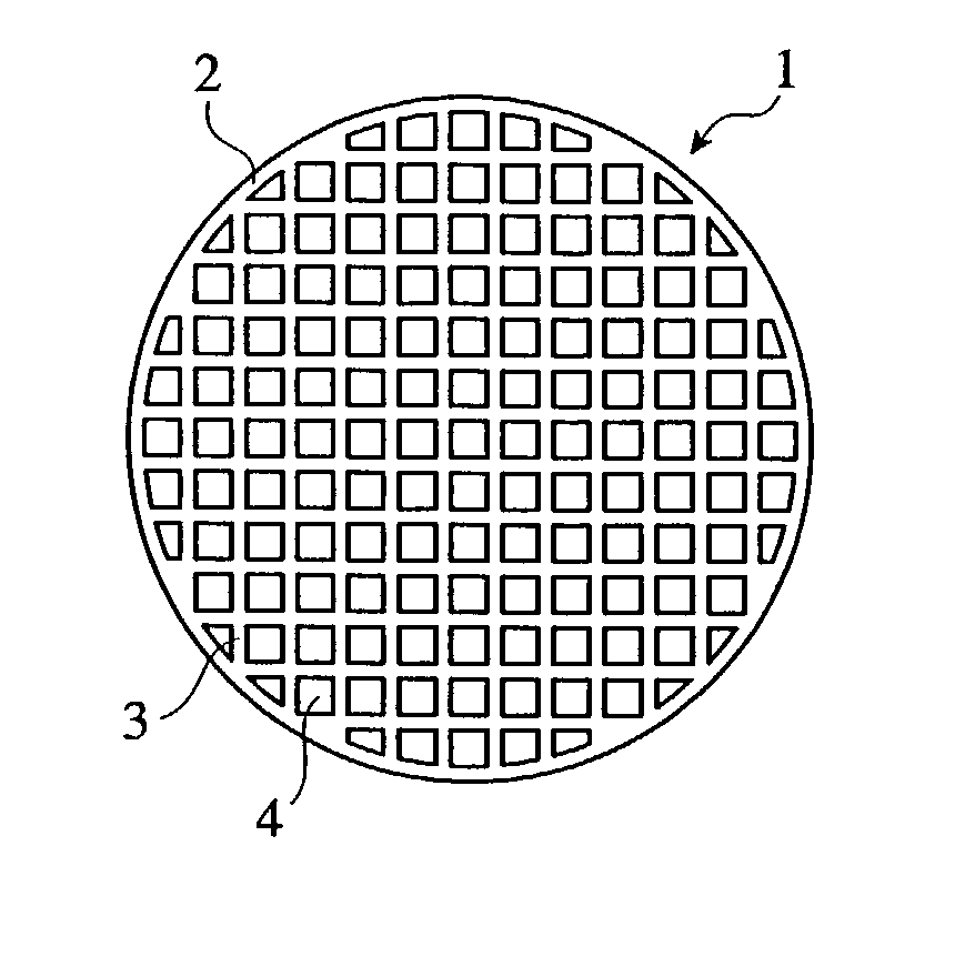
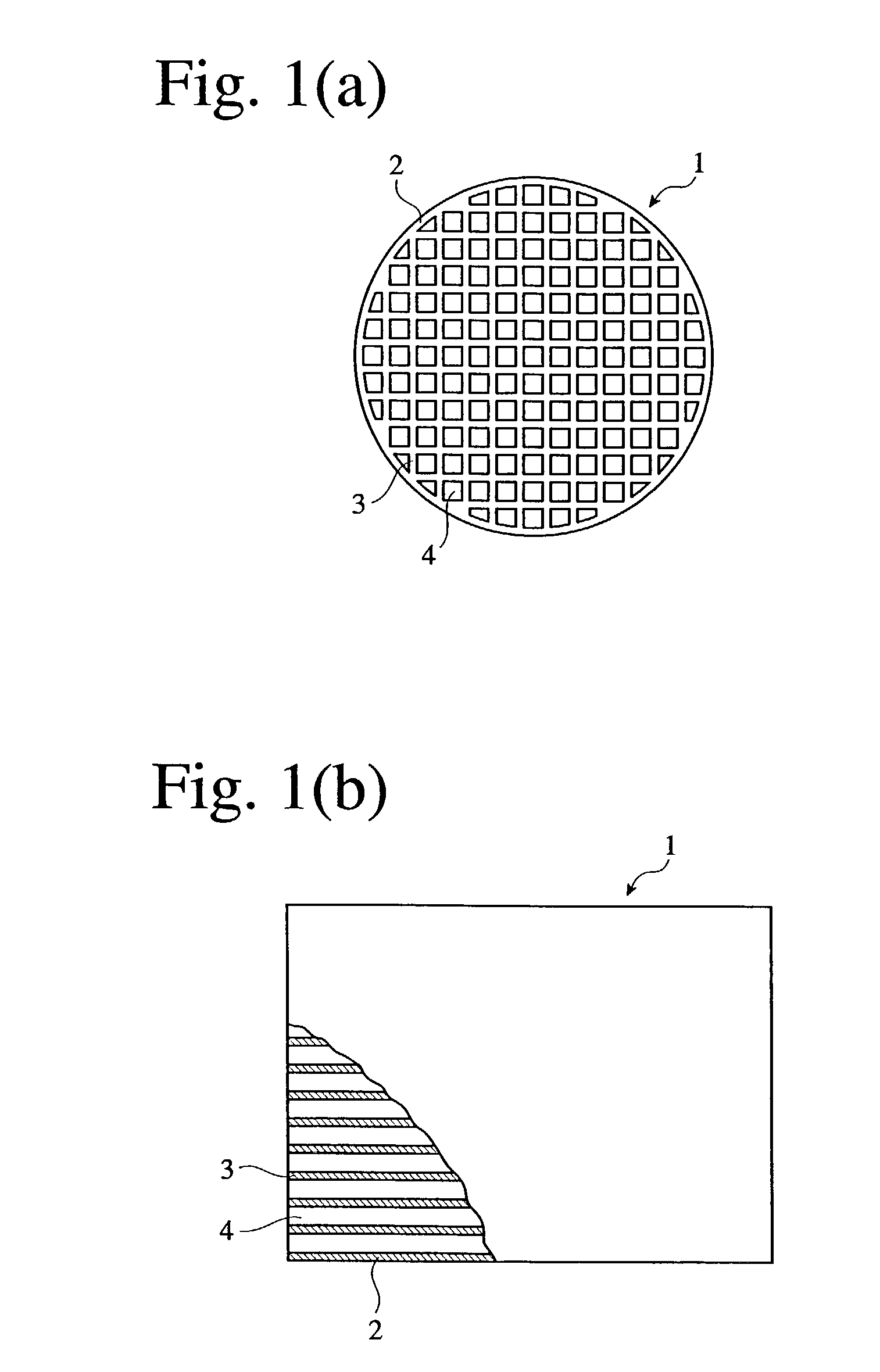
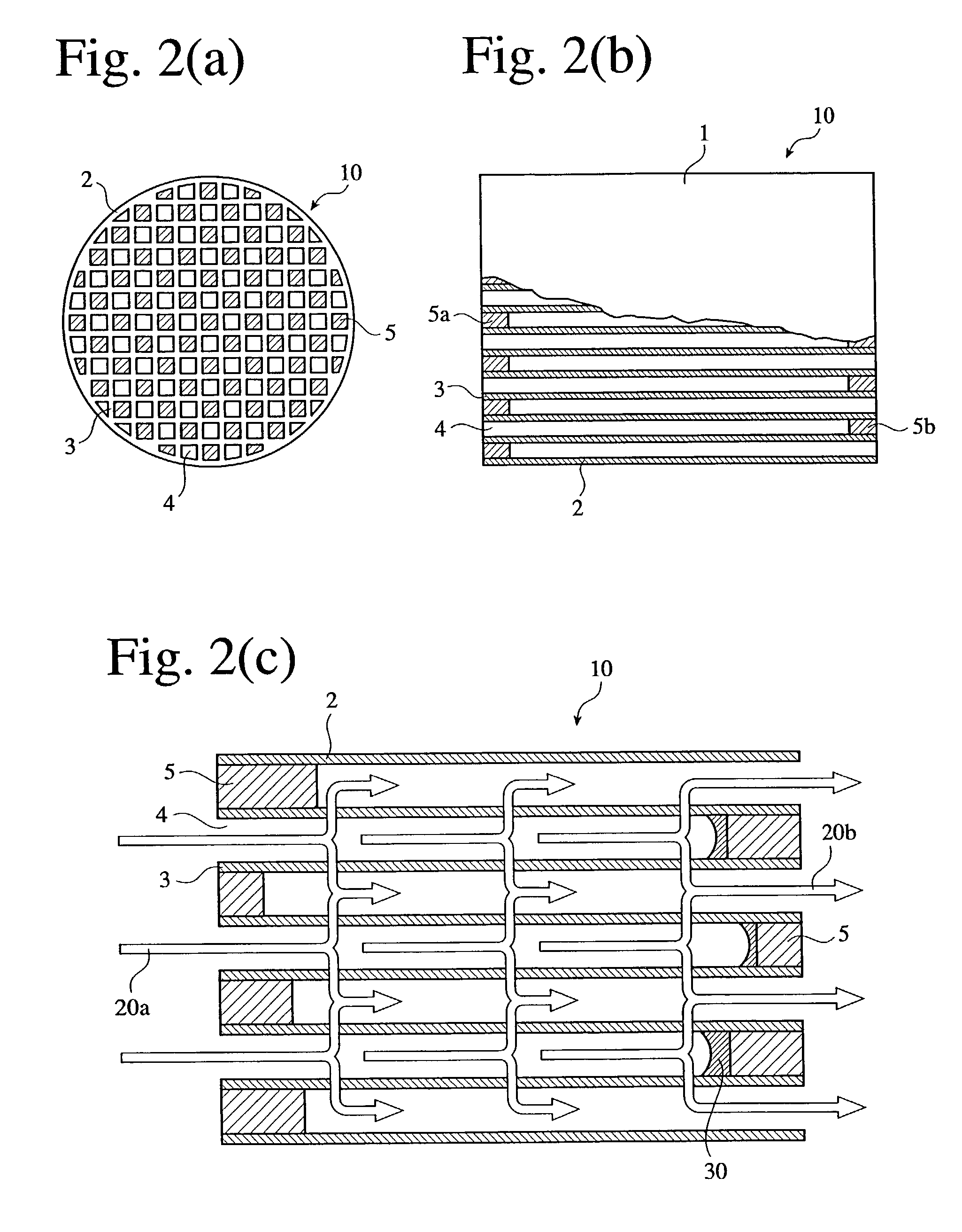
[0001] The present invention relates to a ceramic honeycomb filter for capturing particulates in exhaust gases of automobiles, particularly those from diesel engines, and a ceramic honeycomb structure used therefor.[0002] To remove carbon-based particulates from exhaust gases emitted from diesel engines, ceramic honeycomb filters comprising porous ceramic honeycomb structures with both ends alternately sealed are used.[0003] As shown in FIG. 1, a ceramic honeycomb structure 1 is substantially cylindrical (including an elliptic cross section) with partition walls 3 inside an outer wall 2 and a large number of cells (flow paths) 4 encircled thereby. As shown in FIG. 2(b), both ends of the flow paths 4 are alternately sealed by sealers 5a, 5b.[0004] The cleaning an exhaust gas by a honeycomb filter 10 is carried out as shown in FIG. 2(c). The exhaust gas 20a flows into the flow paths 4 of the honeycomb filter 10, passes through pores in the porous partition walls 3, and exits from the ...

Claims


Application Information

Patent Timeline
IPC IPC(8): B01D46/24B01J35/04B28B11/00C04B35/10C04B35/185C04B35/19C04B35/565C04B35/584C04B38/00F01N3/022
CPCB01D46/2425Y10T428/24149B01D46/244B01D46/2451B01D46/2459B01D46/2466B01D46/247B01D46/2474B01D2046/2433B01D2046/2437B01D2046/2496B01J35/04B28B11/006B28B11/007C04B35/10C04B35/185C04B35/19C04B35/195C04B35/565C04B35/584C04B38/0009C04B2111/0081C04B2235/3203C04B2235/77C04B2235/96C04B2235/9607F01N3/0222F01N2330/06F01N2330/30B01D46/2429Y10T428/24157Y02T10/20C04B38/0012Y10T428/249975Y10T428/249981Y10T428/249953Y02T10/12B01D46/2498B01D46/24492B01D46/24491B01D46/2482B01J35/56B01D46/249
Inventor SUWABE, HIROHISAOKAZAKI, SHUNJITOKUDOME, OSAMUOTSUBO, YASUHIKO
Owner HITACHI METALS LTD
Learn More