
Prismatic ceramic heater for heating gas sensor element, prismatic gas sensor element in multilayered structure including the prismatic ceramic heater, and method for manufacturing the prismatic ceramic heater and prismatic gas sensor element

a technology of prismatic ceramic heaters and sensors, applied can solve problems such as thermal shock, sensor elements may crack or break, and ceramic heaters may not be used in the field of gas sensors

Active Publication Date: 2003-08-28
NGK SPARK PLUG CO LTD
View PDF6 Cites 79 Cited by
  • Summary
  • Abstract
  • Description
  • Claims
  • Application Information

AI Technical Summary

Benefits of technology

[0009] A second object of the present invention is to provide a prismatic ceramic heater for heating a gas sensor which is free from cracking or breakage of an edge portion even upon contact with a liquid substance such as a water droplet, as well as to provide a prismatic ceramic sensor using the prismatic ceramic heater and being free from such cracking or breakage.

Problems solved by technology

Upon contact with such a substance, particularly with a water droplet, a sensor element may crack or break.
Since the sensor element or a ceramic heater is exposed to heat of an engine, contact with a water droplet or the like raises a great temperature difference between a portion in contact with the water droplet and its adjacent portion, thereby inducing thermal shock.
Such thermal shock may cause a breakage of the sensor element or the ceramic heater.
However, the protector fails to provide protection against a liquid substance that readily passes through the ventilation holes.
However, various environmental tests which the present inventors have conducted for feasibility study have revealed the following: even when the surface of a prismatic sensor element is coated with a porous protective layer by a method disclosed or suggested in the above-mentioned publications, contact of a liquid substance, such as a water droplet or oil, with a longitudinally extending edge portion defined by the upper or lower surface and a side surface of the prismatic sensor element, particularly with part of the edge portion located in the vicinity of a heating resistor, induces cracking at the edge portion, and the crack develops to break the prismatic sensor element.
This cracking problem arises because the conventional methods do not pay attention to water-induced-shock resistance of such an edge portion.
When the porosity or thickness falls below the lower-limit, the porous protective layer fails to absorb stress induced by thermal shock which, in turn, is induced by contact with water, thereby failing to prevent cracking in an edge portion of the ceramic heater.
However, the sequence (P1) involves the following disadvantage: since firing conditions must be strictly controlled in consideration of difference in firing contraction coefficient between the laminate and the material powder, a limit may be imposed on the thickness of the green ceramic powder layer to be formed in step (C4); therefore, a required thickness may fail to be imparted to the green ceramic powder layer.
However, the sequence (P2) involves the following disadvantage: the intergranular bonding strength of the porous protective layer may be weakened, or the anchoring strength of the porous protective layer may be weakened in relation to fixation to the prismatic laminate.
In the case where the thickness is less than 20 .mu.m, the protective layer fails to prevent cracking of the ceramic heater or gas sensor element upon contact with water.
In the case where the porosity is in excess of 65%, when water adheres to the protective layer, the amount of water passing through the protective layer increases; consequently, the prismatic ceramic heater or gas sensor element may fail to be sufficiently protected.
However, since accurately controlling porosity variations and the thermal spraying position is difficult, thermal spraying is not suitable for actual production of ceramic heaters or gas sensor elements according to the present invention.
Particularly, in manufacture of a multilayered gas sensor element, thermal spraying involves a problem in that a thermally sprayed layer is also formed on the electrode-protecting layer; as a result, sensor functions are impaired; for example, sensor response slows down.
When the alumina content is less than 70% by mass, the insulating-ceramic element fails to sufficiently exhibit both insulating property and heat resistance.
Such migrating metal ions cause the heating resistor to thin or break.
Therefore, the low-potential portion of the heating resistor is apt to deteriorate or break.
A new glass phase formed around the ion-detaining conductor as mentioned previously could weaken ceramic strength in the region, possibly causing the heating resistor to become detached from the gas sensor element.

Method used


Image

  • Prismatic ceramic heater for heating gas sensor element, prismatic gas sensor element in multilayered structure including the prismatic ceramic heater, and method for manufacturing the prismatic ceramic heater and prismatic gas sensor element
  • Prismatic ceramic heater for heating gas sensor element, prismatic gas sensor element in multilayered structure including the prismatic ceramic heater, and method for manufacturing the prismatic ceramic heater and prismatic gas sensor element
  • Prismatic ceramic heater for heating gas sensor element, prismatic gas sensor element in multilayered structure including the prismatic ceramic heater, and method for manufacturing the prismatic ceramic heater and prismatic gas sensor element

Examples


Embodiment Construction

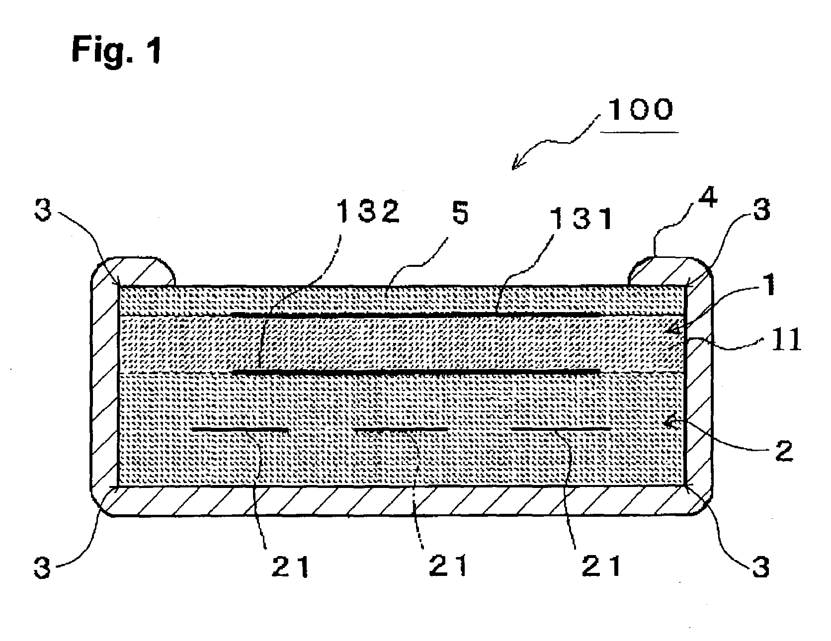
[0163] As is apparent from the test results shown in Tables 1 and 2, almost all samples are free from cracking in the water drop test (0.3 .mu.l and 1.0 .mu.l) conducted on their back surfaces. However, in the case of the samples in which the porous protective layer 4 is not formed on its edge portions 3, three elements out of 10 are cracked in the water drop test conducted on the edge portion 3 at an amount of water droplet of 0.3 .mu.l. Further, in the water drop test conducted at a severe amount of water droplet of 1 .mu.l, more than half the samples are cracked. These test results indicate that a sample having no porous protective layer 4 formed thereon is prone to crack upon adhesion of water to at least the edge portion 3.

[0164] By contrast, the samples in which the porous protective layer having a thickness not less than 20 .mu.m is formed on at least the edge portions 3 are free from cracking in the water drop test in which water was dropped on at least the edge portion 3 in...


PUM

PropertyMeasurementUnit
thicknessaaaaaaaaaa
thicknessaaaaaaaaaa
curvature radiusaaaaaaaaaa

Abstract

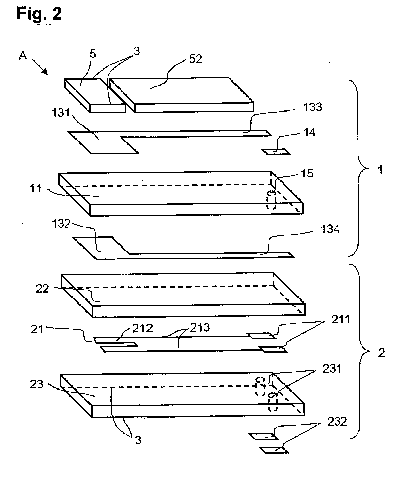
A prismatic ceramic heater for heating a gas sensor element includes a heating resistor embedded in ceramic, and has a substantially rectangular cross section. At least part of a longitudinally extending edge portion of the prismatic ceramic heater is located in the vicinity of the heating resistor. This part of the longitudinally extending edge portion is coated with a porous protective layer. The protective layer has a thickness not less than 20 mum and a curved surface of a curvature radius not less than 10 mum. The protective layer prevents cracking induced by contact with water.

Description

[0001] 1. Field of the Invention[0002] The present invention relates to a gas sensor, such as an oxygen sensor, an A / F sensor, an NO.sub.x sensor, or an HC sensor, for use in, for example, controlling exhaust gas from an internal combustion engine of an automobile. More particularly, the invention relates to a prismatic multilayered gas sensor element; a prismatic ceramic heater of a substantially rectangular cross section for heating the prismatic multilayered gas sensor element; a prismatic multilayered gas sensor element to be arranged integrally with the prismatic ceramic heater; a method for manufacturing the prismatic ceramic heater and the prismatic multilayered gas sensor element; and a gas sensor including the prismatic ceramic heater and / or the prismatic multilayered gas sensor element. The invention further relates to a method for manufacturing a prismatic ceramic heater of a substantially rectangular cross section for heating a gas sensor and a prismatic gas sensor eleme...

Claims


Application Information

Patent Timeline
Patent Type & Authority Applications(United States)
IPC IPC(8): G01N27/406
CPCG01N27/4067
Inventor KOJIMA, TAKAOMAKINO, KEISUKEAWANO, SHINYA
Owner NGK SPARK PLUG CO LTD
Learn More