Integrated pneumatic manifold
a pneumatic manifold and integrated technology, applied in the field of electropneumatic installation, can solve the problems of time delay and down the tube, and achieve the effects of reducing skill levels, ensuring repeatability and quality, and being easy to meet and control
- Summary
- Abstract
- Description
- Claims
- Application Information
AI Technical Summary
Benefits of technology
Problems solved by technology
Method used
Image
Examples
Embodiment Construction
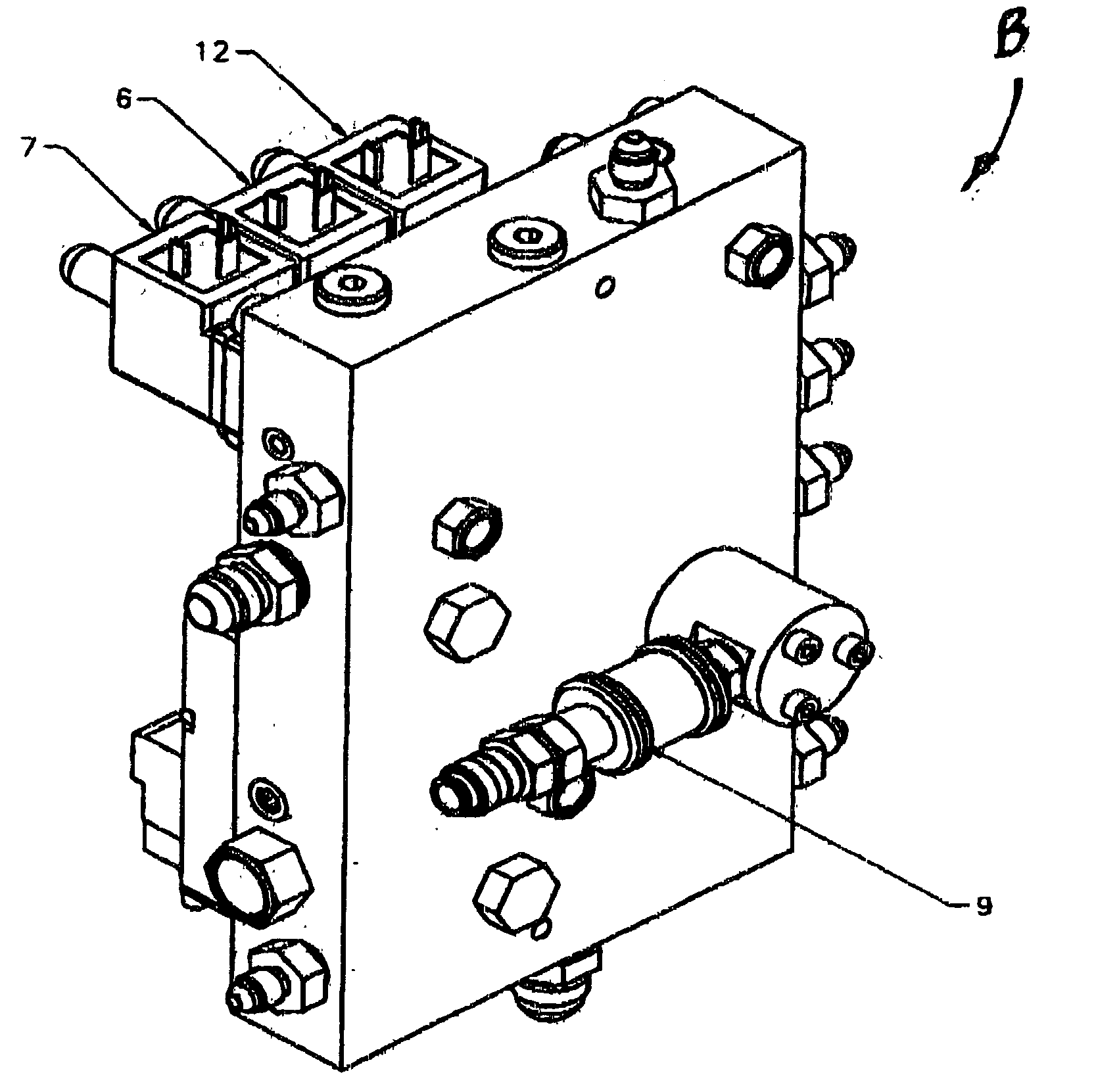
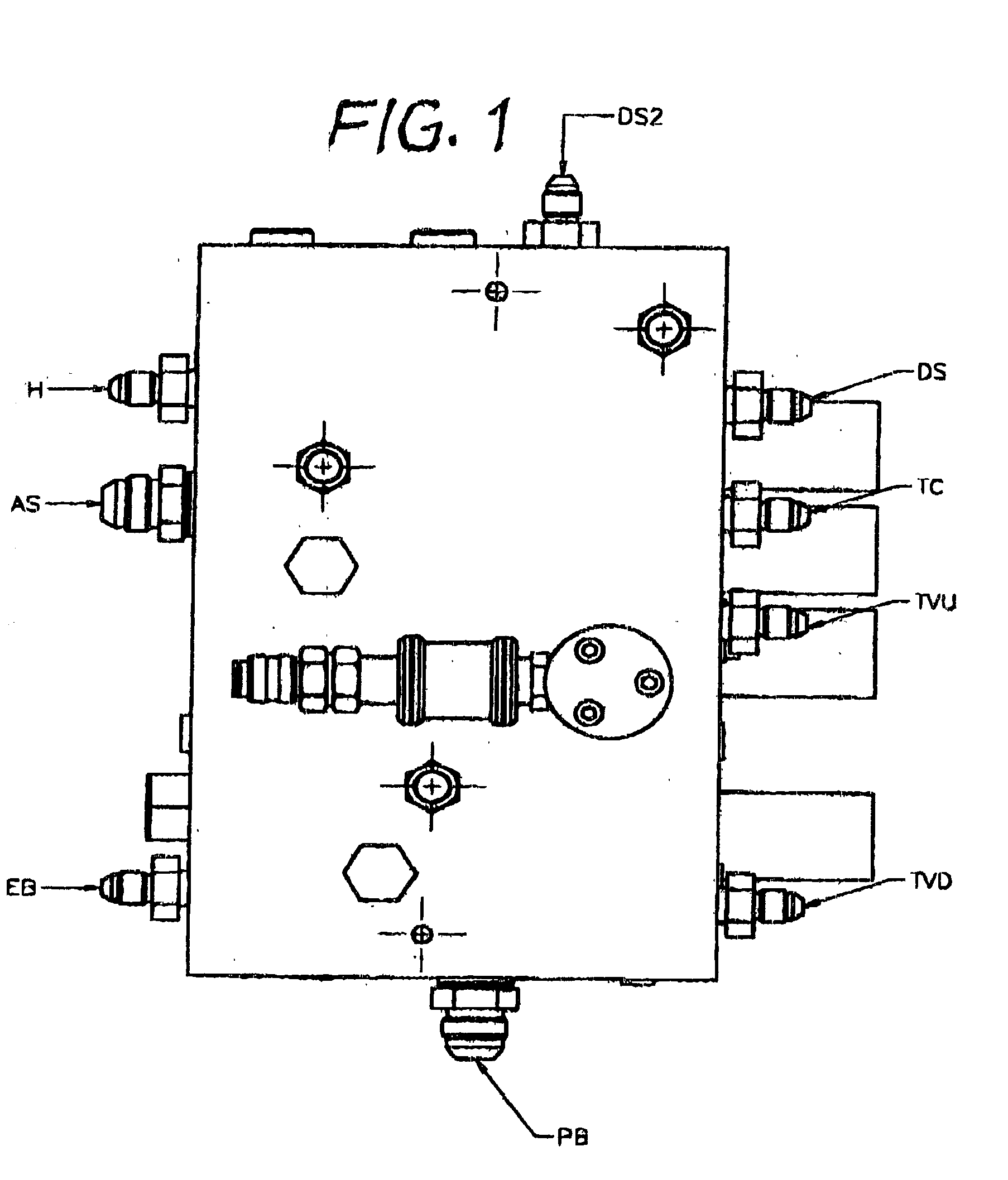
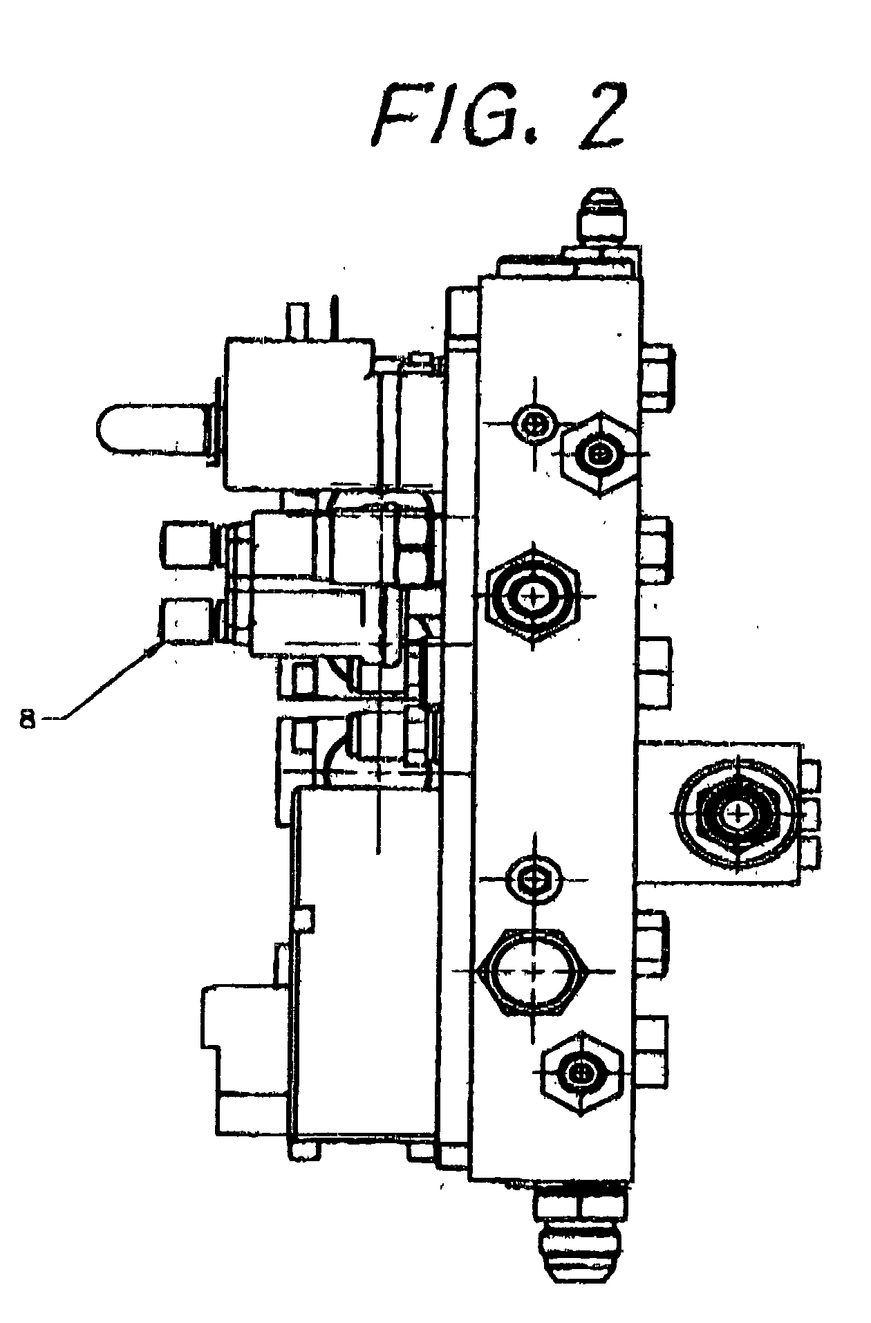
[0025] The preferred embodiment is shown in the drawings. It is an example, which can be used for heavy vehicles. It comprises a block 8, which is rectangular in its shape, only high quality Swiss aluminium is used to ensure non-porosity. Components are selected from suppliers in Germany, England, Switzerland, Spain and USA. The design uses ISO and other world wide accepted standards to ensure interchange of components from various suppliers.
[0026] The integrated pneumatic manifold is machined using a four axis CNC machining centre and modifications can be made in minutes using this system as opposed to injection moulding in which changes can not be made economically. This makes the system suitable for short production runs which are experienced typically in second and third tier industrialized countries and also in some cases in first tier industrialized countries.
[0027] The components that are on the protected side of the block include solenoids 1, 2, 6 and 7, pressure switches 3,...
PUM
 Abstract
Description
Claims
Application Information
 - R&D
- Intellectual Property
- Life Sciences
- Materials
- Tech Scout
- Unparalleled Data Quality
- Higher Quality Content
- 60% Fewer Hallucinations
Browse by: Latest US Patents, China's latest patents, Technical Efficacy Thesaurus, Application Domain, Technology Topic, Popular Technical Reports.
© 2025 PatSnap. All rights reserved.Legal|Privacy policy|Modern Slavery Act Transparency Statement|Sitemap|About US| Contact US: help@patsnap.com


