
Frozen beverage machine and method of operation

a beverage machine and frozen technology, applied in the field of frozen beverage machines, can solve the problems of reducing the reliability of the disassembly and cleaning process, affecting the quality of the product to be dispensed, and retarding the growth of contaminants, so as to reduce the exposure to contamination and subsequent growth of contaminants, and minimize any exposure to contaminants

Inactive Publication Date: 2003-07-10
FBD PARTNERSHIP
View PDF1 Cites 39 Cited by
  • Summary
  • Abstract
  • Description
  • Claims
  • Application Information

AI Technical Summary

Benefits of technology

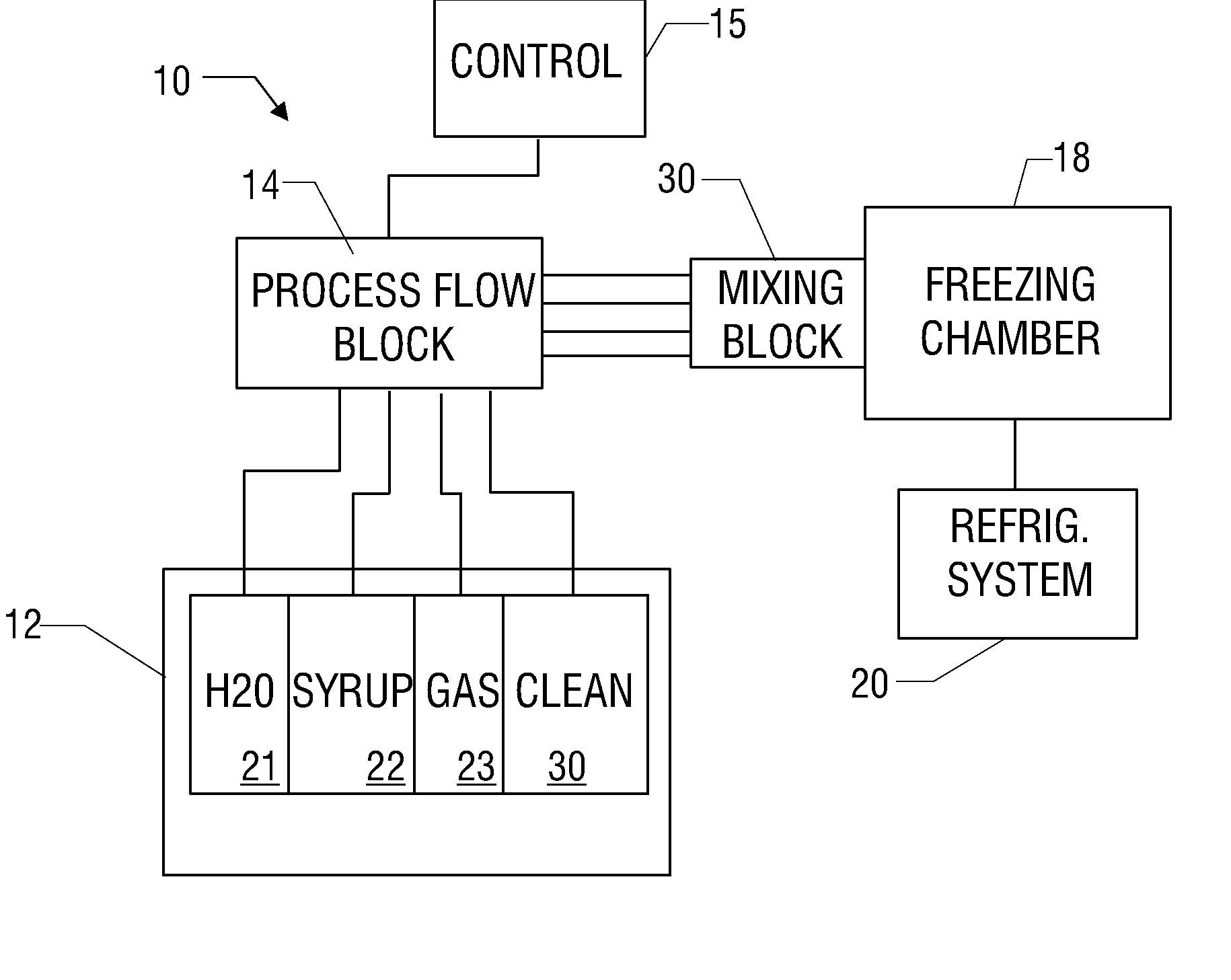
[0009] The present invention addresses some of these issues associated with the prior art and significantly reduces the contamination exposure and subsequent growth of contaminants by the provision of a sealed machine with a sealed delivery system. It will minimize any exposure to contaminants while keeping the mixture refrigerated in order to retard growth of any small amounts of contaminants that may enter the sealed system. The system and methods according to the present invention are particularly suited in processing beverages that are subject to microbiological contamination and growth, such as milk products or other protein based beverages or simple sugar based beverages. Further, while the present invention is disclosed primarily in terms of frozen beverages, it is applicable to any containerized or flow system.

Problems solved by technology

In so doing, any contaminants that are introduced will have their growth retarded by the low temperatures.
While these existing machines can retard the growth of contaminants, the contaminants do continue to grow and the hoppers are exposed to air-borne contaminates, so the machines must be sanitized on a periodic basis.
This is somewhat effective, but has a negative effect on the quality of the product to be dispensed.
Moreover, the reliability of the disassembly and cleaning process is often low due, as unskilled and under-trained individuals are often required to complete this process.

Method used


Image

  • Frozen beverage machine and method of operation
  • Frozen beverage machine and method of operation
  • Frozen beverage machine and method of operation

Examples


Embodiment Construction

[0031] Illustrative embodiments of the invention are described below. In the interest of clarity, not all features of an actual implementation are described in this specification. It will of course be appreciated that in the development of any such actual embodiment, numerous implementation-specific decisions must be made to achieve the developers' specific goals, such as compliance with system-related and business-related constraints, which will vary from one implementation to another. Moreover, it will be appreciated that such a development effort might be complex and time-consuming, but would nevertheless be a routine undertaking for those of ordinary skill in the art having the benefit of this disclosure.

[0032] The invention of this disclosure provides modifications and improvements to frozen beverage machines, such as the machines and systems disclosed in U.S. Patent Nos. 5,706,661; 5,743,097; 5,799,726; and 5,806,550 by J.I. Frank. The entire disclosures of these patents are i...


PUM


Abstract

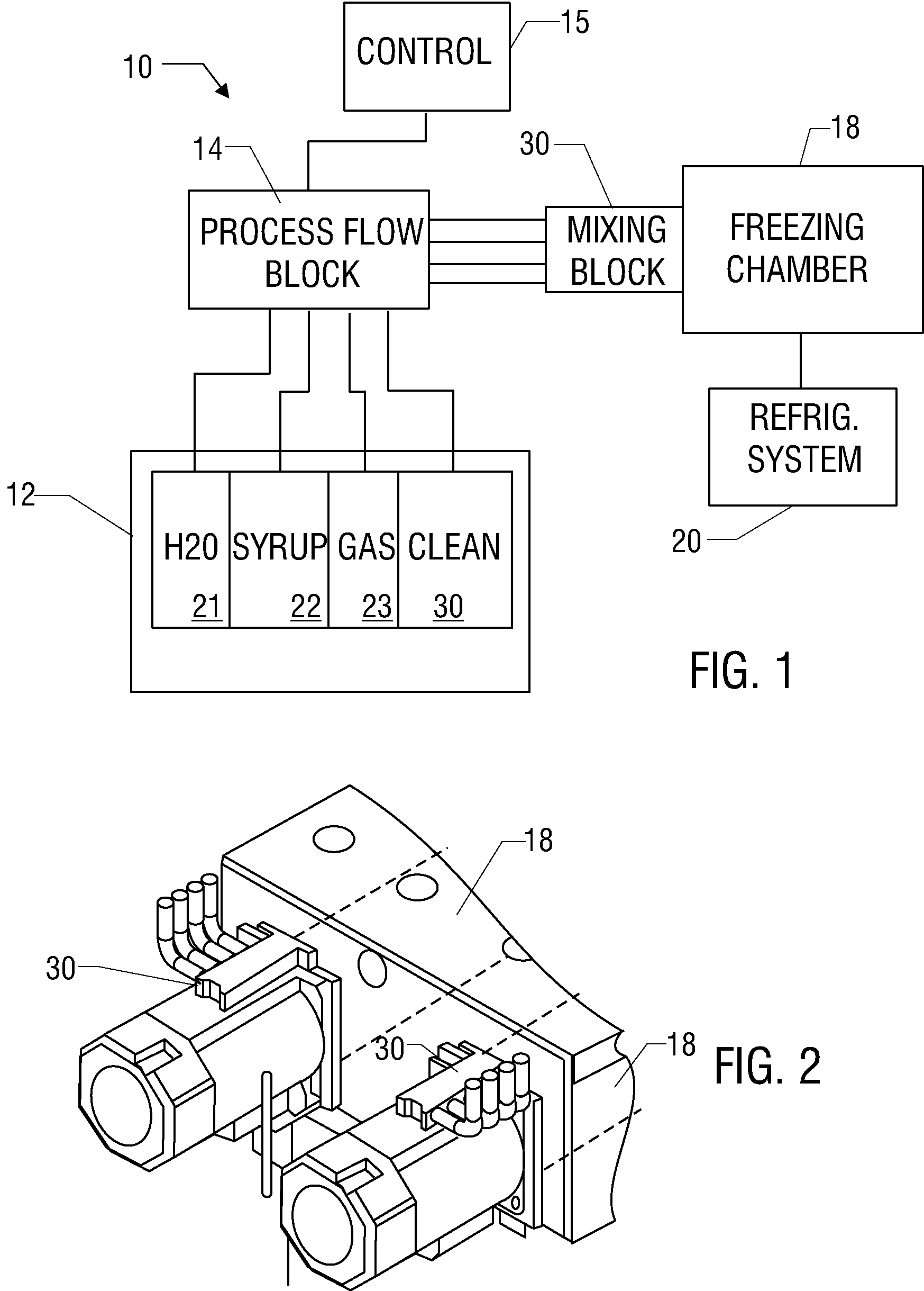
Abstract of Disclosure A frozen beverage machine includes a mixing block having a plurality of inlets and an outlet coupled to a freezing chamber. The freezing chamber has a drain valve and a dispensing valve coupled thereto. Beverage ingredients are pumped into corresponding ingredient inlets of the mixing block such that the ingredients are mixed in the mixing block to form a product mixture, and the product mixture flows from the mixing block outlet into the freezing chamber. The freezing chamber and the mixing block are refrigerated. The product mixture is drained from the freezing chamber via the drain valve, and a cleaning solution is pumped into a cleaning solution inlet of the mixing block and into the freezing chamber. The cleaning solution is drained from the freezing chamber via the drain valve.

Description

Cross Reference to Related Applications[0001] This application is a division of U.S. Patent Application Serial No. 09 / 932,454, filed on August 18, 2001, which is incorporated by reference in its entirety.Background of Invention[0002] Field of the Invention.[0003] The invention relates generally to beverage machines, and more particularly, to devices and methods for producing and dispensing products that are susceptible to growth of microbiological organisms.[0004] Description of Related Art.[0005] Systems for producing beverages, such as frozen carbonated beverage machines, are well known in the art. These devices produce a frozen beverage by freezing a mixture of ingredients such as syrup, water and carbon dioxide in a mixing, or freezing, chamber. The mixture freezes on the inner surface of the refrigerated mixing chamber. Typically, the mixing chamber is surrounded by a helical coil through which a refrigerant passes. A beater is disposed inside the chamber, which includes a rota...

Claims


Application Information

Patent Timeline
IPC IPC(8): A23G9/04A23G9/20A23G9/22A23G9/28A23G9/30F25C1/14
CPCA23G9/045A23G9/20A23G9/228F25C2400/12A23G9/281A23G9/30F25C1/14A23G9/28
Inventor FRANK , JIMMY IGUY , THOMAS L III
Owner FBD PARTNERSHIP
Learn More