
High lumen LED solar sign

a solar panel and led light technology, applied in the direction of electric lighting with batteries, lighting and heating equipment, instruments, etc., can solve the problems of poor image quality, poor color reproduction effect, and inability to use ordinary copy paper, etc., to achieve low voltage and little or no heat

Inactive Publication Date: 2003-06-05
NOLAN STEVEN T
View PDF0 Cites 17 Cited by
  • Summary
  • Abstract
  • Description
  • Claims
  • Application Information

AI Technical Summary

Benefits of technology

[0007] The primary objective of the invention is to provide a solar powered sign using bright white LED lamps behind a white translucent dispersion panel whereupon transparent signage, plain white paper signs or lettering may be displayed where there is no power available, the bright white LED lamps providing advantages over other conventional lighting by requiring low voltage, giving off little or no heat and having a life span of over 100,000 hours.
[0009] The present invention, in using the white translucent display panel between the high lumen light source and the display image allows for production of display medium using a simple home computer printer on white paper or simple low-cost print shop technique. The white translucent display panel evenly disperses the light from the high lumen light source and also maintains the integrity of the colors. White actually appears white and is of an even intensity, reducing bright spots through the display medium. Colors experience less darkening and distortion due to the white translucent display panel maintaining a uniform light dispersion back-lighted image. Childrens artwork, digital photographs on white paper, transparencies or text messages can all be displayed with clear visual accuracy of the printed or displayed subject matter.
[0012] Using the bright white LEDs minimized the amount of required power for operation and prolongs the time the stored energy may be drawn before exhausting the stored power supply. It also makes replacement of the bulbs a non-issue, since these LEDs have a life span of nearly 100 times that of the more conventional lighting bulbs.

Problems solved by technology

This generally requires use of a professional print shop, which is generally not available for home production or use.
Printers and copiers are not equipped with white ink.
When the light is directed through this display medium, the image seen is severely distorted by the direct unfiltered light through the clear portion of the image being displayed.
Ordinary copy paper cannot be used, because it tends to become dark and images printed in dark color on this medium tend to lose their color because of the density of the ink in contrast to lighter colors.
With incandescent bulbs, almost 85% of the energy used in the bulb is given off as heat making them quite inefficient as a light source.
Due to their design, these bulbs have a very short life span and require frequent replacement.
A great deal of lighted device design is concerned with protection from heat or requiring the incorporation of small low wattage low lumen bulbs, due to the excessive heat produced by conventional incandescent bulbs.

Method used


Image

  • High lumen LED solar sign
  • High lumen LED solar sign
  • High lumen LED solar sign

Examples


first embodiment

[0020] In the device, which is a single-sided display device, the sign encasement 20 has an outer surface 22 and an internal cavity 24 which contains the internal bright white LED light source 30, provided by a plurality of bright white LED lamps 32 set in front of a reflective backing plate 26, the bright white LED lamps 32 producing a high lumen output with low voltage DC power supplied by the internal rechargeable battery supply 55 connected to the plurality of bright white LED lamps 32 by the electrical circuitry 60, as shown in FIG. 2 of the drawings. The internal rechargeable battery supply 55 is connected to the external solar generating unit 80, also through electrical circuitry 60.

[0021] The white translucent dispersion panel 40 is positioned in front of the bright white LED light source 30 and the internal rechargeable battery supply 55. This white translucent dispersion panel 40 has a front surface 42 upon which the sign display medium 45 is placed. The transparent front ...

second embodiment

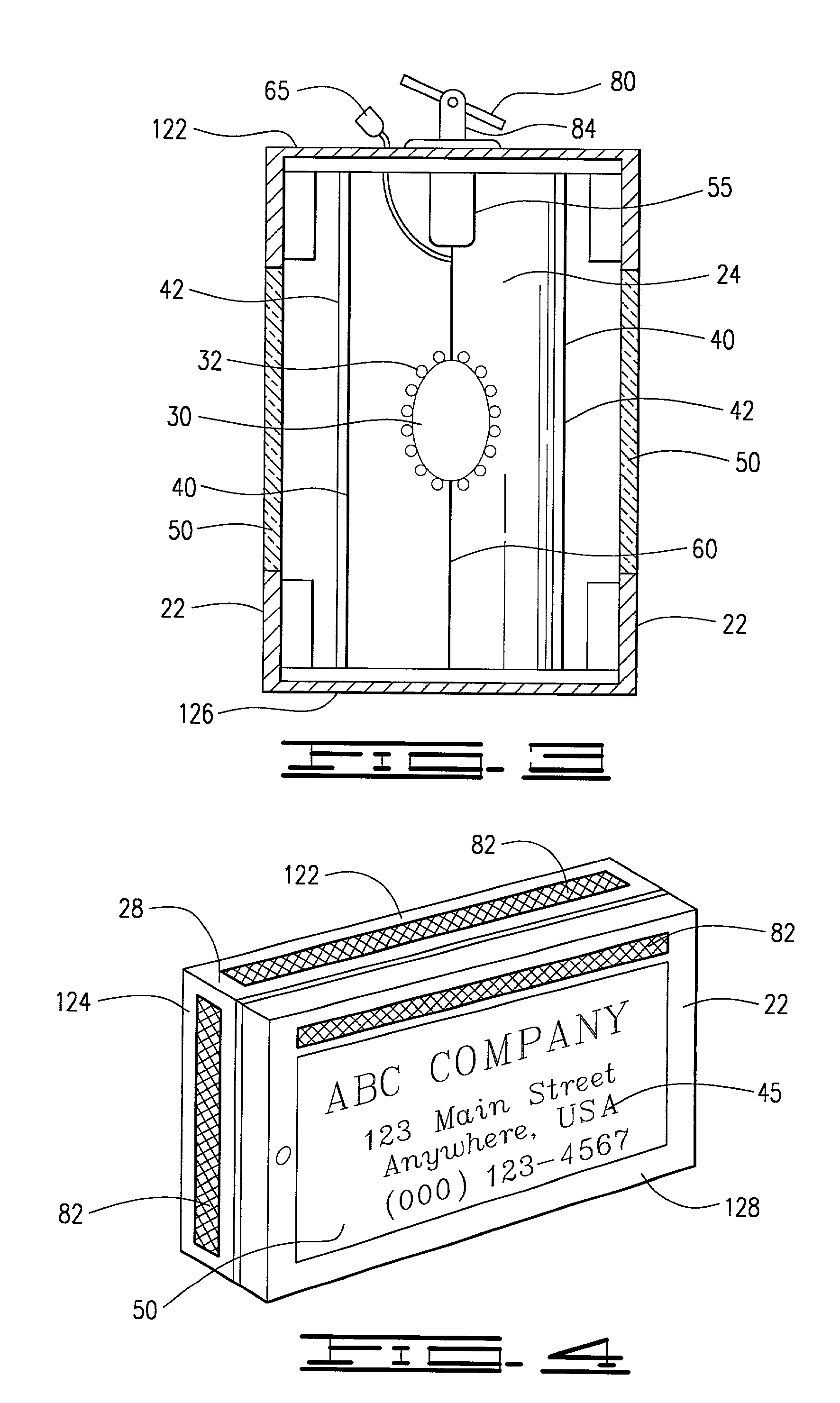
[0022] In the device, as shown in FIG. 3 of the drawings, a two-sided display device is indicated. This two-sided display device also includes a sign encasement 20 having an outer surface 22 and an inner cavity 24. The two-sided display device further includes the bright white LED light source 30, again provided by a plurality of bright white LED lamps 32 producing a high lumen output with low voltage DC power supplied by the internal rechargeable battery supply 55 connected to the bright white LED lamps 32 by the electrical circuitry 60, the internal rechargeable battery supply 55 connected to the external solar generating unit 80, also through electrical circuitry 60.

[0023] However, the two-sided display device has two white translucent dispersion panels 40 positioned on opposing sides of the bright white LED light source 30 and the internal rechargeable battery supply 55. Each of these white translucent dispersion panels 30 have a front surface 32 upon which the sign display medi...


PUM


Abstract

The invention is a self-contained solar powered back lighted sign using low voltage bright white LED lamps for a light source, the device comprising a sign encasement, an internal bright white LED light source, at least one white translucent dispersion panel, sign display medium, at least one transparent front panel, an internal rechargeable battery supply, electrical circuitry, a photo sensor and an at least one external solar generating unit. Plain white paper signs, transparencies and changeable lettering may by displayed in this device, providing for repeated low-cost change of the display medium on the device, the device being perpetual and self-contained providing its own cost-free electrical energy.

Description

[0001] NoneI. Background of the Invention[0002] 1. Field of Invention[0003] The invention is a self-contained solar powered back-lighted sign using low voltage bright white LED lamps for a light source, including a sign encasement, an internal bright white LED light source, one or more white translucent dispersion panel, sign display medium, one or more transparent front panel, an internal rechargeable battery supply, electrical circuitry, a photo sensor and an at least one external solar generating unit. Plain white paper signs, transparencies and changeable lettering may by displayed in this device, providing for repeated low-cost change of the display medium on the device, the device being perpetual and self-contained providing its own cost-free electrical energy.[0004] 2. Description of Prior Art[0005] The following United States patents were discovered and are disclosed within this application for utility patent. All relate to outdoor signs. A first sign is disclosed in U.S. Pa...

Claims


Application Information

Patent Timeline
Patent Type & Authority Applications(United States)
IPC IPC(8): G09F13/04
CPCG09F13/04
Inventor NOLAN, STEVEN T.
Owner NOLAN STEVEN T
Learn More