
Ion source

a technology of ion beam and beam current, applied in the field of ion beam, can solve the problems of limited beam current supply, difficult to supply a large electric current in view of the capacity of the extraction power source, and the limitation of the whole beam curren

Inactive Publication Date: 2003-05-22
NISSIN ION EQUIP CO LTD
View PDF1 Cites 5 Cited by
  • Summary
  • Abstract
  • Description
  • Claims
  • Application Information

AI Technical Summary

Benefits of technology

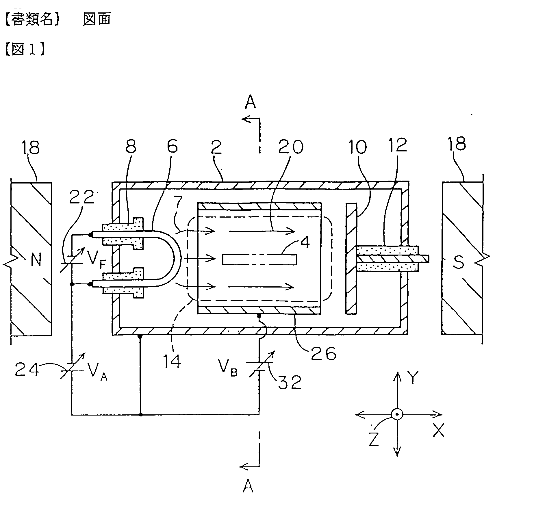
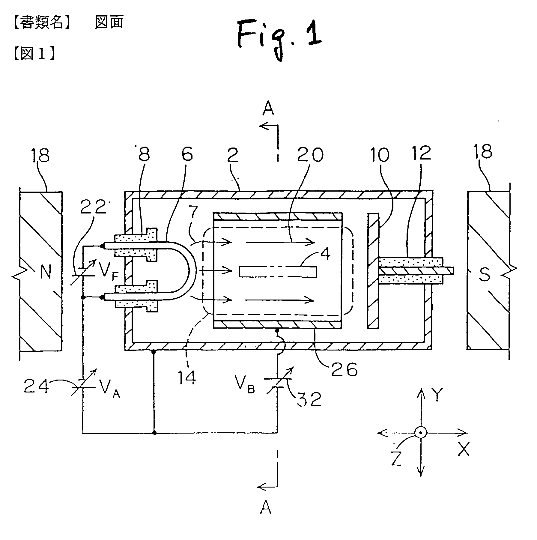
[0019] The ion in plasma produced in the plasma production chamber is pushed back toward the plasma, because the ion in plasma has the same polarity as the positive electrode, by the positive bias voltage applied to the positive electrode, in the wall surfaces other than the opening of the positive electrode. The pushed back ion is subject to collision by the primary electron produced mainly in the electron producing source, so that the charged number is increased. Generally as to the rate of the ion producing possibility of n charged (n.gtoreq.2) ion, compared to (a) the possibility to produce the n charged ion from a neutral gas, (b) the possibility to produce the n charged ion from an n-1 charged ion is by far large. According to the ion source, since the process of (b) may be efficiently utilized by use of the pushed-back ion (namely, what is already ionized), the multiply charged ion may be efficiently produced.
[0022] In the neighborhood of the thus produced plasma, there is the positive electrode to be applied with the positive bias voltage from the bias power source. The secondary electron released at the time of collision of the primary electron with the neutral gas has the comparatively low energy as above mentioned and is released indefinitely in many directions. Thus, owing to existence of the positive electrode in the neighborhood of the plasma, the secondary electron in the neighborhood of the positive electrode is absorbed by the positive electrode of different polarity. The quantity of the secondary electron existing in the plasma is reduced as well accordingly. Incidentally, since the primary electron produced from the electron producing source has a comparatively high directivity and is trapped by the magnetic field to move along the magnetic field, the rate of the primary electron absorbed by the positive electrode is far smaller than the secondary electron. In order to further reduce the rate of the primary electron absorbed by the positive electrode, it is preferred to more intensify the magnetic field produced by the magnetic field generator so as to cause the magnetic field to intensively trap the primary electron.
[0024] With the actions of the preceding (1) and (2), the rate of the multiply charged ion in the plasma may be increased, and in turn the rate of the multiply charged ion contained in the ion beam may be increased. As a result, the quantity of the multiply charged ion to be extracted may be increased without totally increasing the ion beam current (ion beam extraction quantity).

Problems solved by technology

However, in case the whole ion beam current is increased so much, an electrode system for extracting the ion beam will cause troubles including beam current limitation owing to a space charge effect or occurrence such as discharge between electrodes.
Further, although electric current applied to the power source for supplying an extraction voltage to the extraction electrode system becomes large, it is difficult to supply a large electric current in view of capacity of the extraction power source.
Therefore, a limitation is present to increase the whole beam current, and it is difficult to increase the quantity of the multiply charged ion taking such measures.

Method used


Image

  • Ion source
  • Ion source
  • Ion source

Examples


Embodiment Construction

60 60 0.6

[0057] As shown in the Table 1, irrespective of the substantial arc voltage V.sub.S and the magnetic field 20 at the same intensity, the rate of P.sup.3+ ion is about 3 times higher in case of the example than the comparative example. It is, therefore, apparent that provision of the positive electrode 26 and application of the positive bias voltage V.sub.B remarkably contribute to increasing of the rate of multiply charged ion contained in the ion beam 16.

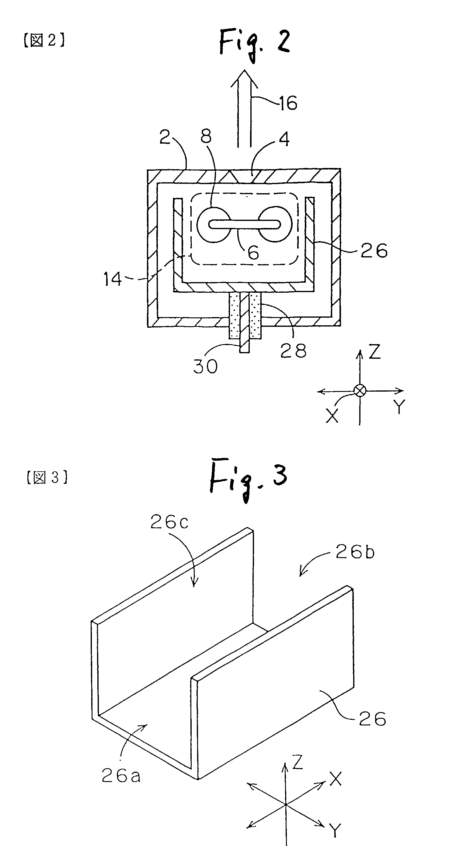
[0058] The shape of the positive electrode 26 may be other than that as shown in FIGS. 1 to 3. For example, as shown in FIG. 5, the positive electrode 26 may be tube or trough shaped with a circular in the cross section along the plane Y-Z. The cross section may be oval.

[0059] The opening 26c, 26c' at the side of the ion extraction opening 4 of the positive electrode 26, 26' may be all opened at the side of the ion extraction opening 4 as shown in FIGS. 1 to 3, or as shown in FIG. 5, for example, the width W of the opening...


PUM


Abstract

An ion source called as a Bernas-type ion source is additionally provided with a positive electrode and a bias power source. The positive electrode is provided in a plasma production chamber and is electrically isolated therefrom. The positive electrode has three openings at least at both sides of a X direction along a magnetic field produced in a magnetic field generator and at a side of an ion extraction opening (a side of ion beam extraction direction). The bias power source applies a positive bias voltage to the positive electrode and to the plasma production chamber. With combination of constituent elements, the positive electrode serves to push back the ion in the plasma and further functions to suck a secondary electron in the plasma, thereby increase the rate of the multiply charged ion in the plasma.

Description

[0001] 1. Field of the Invention[0002] The present invention relates to an ion source of an electronic impact type for producing plasma by ionizing a gas by electronic impact in a magnetic field. More particularly, the present invention relates to an ion source which can increase the rate of multiply charged ion (ion of doubly charged or more) contained in an ion beam to be extracted.[0003] 2. Description of the Related Art[0004] There are various systems of the ion sources of the electronic impact type. One of the examples is disclosed in Patent Laid Open 35648 / 1997, where an ion source of a Bernas-type is described for increasing the density of plasma by using in combination of confinement of electron by a magnetic field and reflection of electron by a reflector.[0005] It has been demanded to extract the multiply charged ion, that is, ion of doubly charged or more, from the ion source for utilizing the same. This is because, in comparison with singly charged ion, the multiply char...

Claims


Application Information

Patent Timeline
IPC IPC(8): G21K1/00B01J19/12H01J27/14H01J37/08
CPCH01J27/14H01J37/08
Inventor YAMASHITA, TAKATOSHI
Owner NISSIN ION EQUIP CO LTD
Learn More