
Dual piston, single phase sampling mechanism and procedure

Inactive Publication Date: 2003-04-10
BAKER HUGHES INC
View PDF15 Cites 87 Cited by
  • Summary
  • Abstract
  • Description
  • Claims
  • Application Information

AI Technical Summary

Benefits of technology

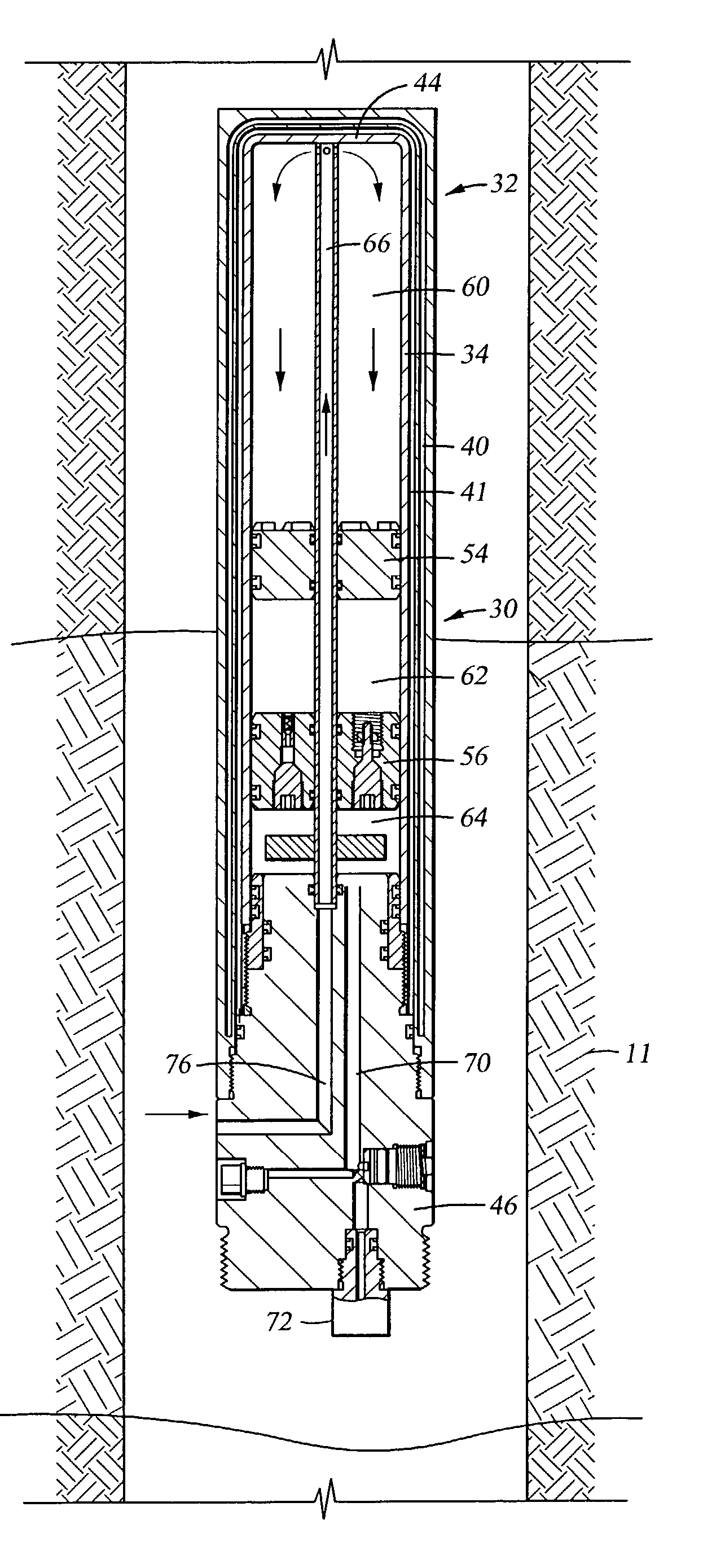
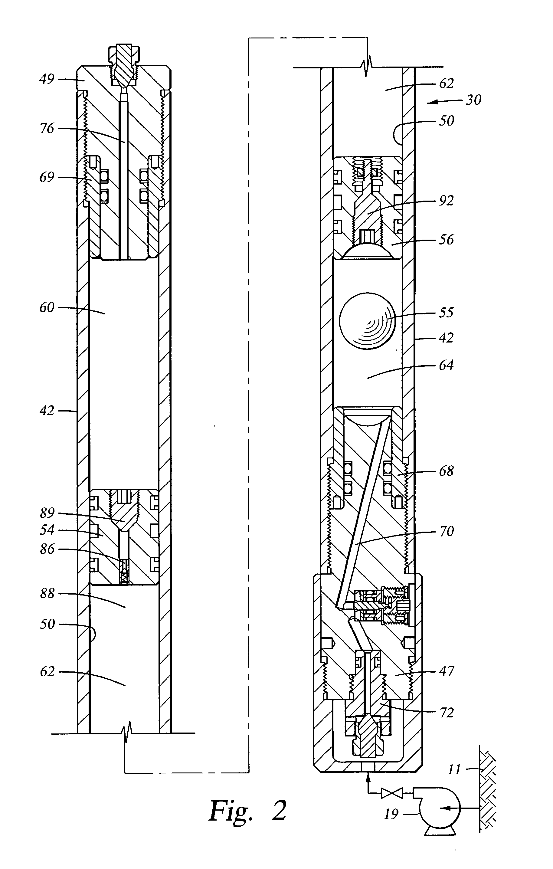
[0026] With the limit sleeve in place, a source of high pressure gas, preferably an inert gas such as nitrogen at about 2000 to 2500 psi, for example, is connected to the first aperture of the second piston to charge the intermediate volume. With the charge complete, the check valve in the first aperture holds the charge in the intermediate volume while the gas source is disconnected. When the disconnection is complete, the first aperture petcock is manually closed to assure no leakage loss past the check valve.
[0028] An additional operative in the present invention is the cooling effect on the formation sample as it enters the plug head volume which has been insulated from the bottomhole heat by the surrounding air and vacuum jacket. As a consequence of the cooling, the formation sample has an increased density at the elevated pump pressure thereby increasing the weight of sample obtained in a given volume.
[0030] At the surface, the wellhead fluid conduit is immediately connected to a high pressure water source, for example, and the cylinder pressure further increased. This additional pressure on the formation sample offsets the density loss due to the ultimate cooling of the sample to the surface ambient thereby preserving the single phase integrity of the sample constituency.
[0031] Following the final water pressure charge, the inner tubular body may be withdrawn from the outer tube vacuum jacket to reduce the weight and bulk for shipment to a remote analysis laboratory.

Problems solved by technology

Further, these properties affect decisions as to whether production may be economically achieved at all and, if so, the duration, expense and unit price of such production.
Such changes may cause certain components of the formation fluid to irreversibly precipitate from solution and / or colloidal suspension and thereby be underestimated by surface sampling.
Well production events such as paraffin or asphaltene deposition, may cause substantial downhole damage to the well.
However, prevention of irreversible changes in a formation sample during retrieval to the surface and discharge into pressurized test or storage devices has remained problematic.
During retrieval of the sample tool to the surface, cooling of the sample, in a fixed volume, resulted in a sample pressure decrease.
While very careful laboratory studies could be conducted on at least a partially recombined sample and further testing could be performed on components irreversibly separated from the original sample, there persisted a margin of possible inaccuracy which was sometimes critical to very valuable production properties.
As those skilled in the art know, some production properties of a formation fluid can be problematic and expensive for cleaning or reworking of the well.
It may be difficult, if not impossible, to restore the well to production following a rework.
Additionally, as the sample cools on retrieval, so does the trapped gas thereby further reducing the ability of the trapped gas to reexpand fully from downhole conditions.
Thus, while tools of group A may be of some utility, at least for the purpose of limiting the amount of pressure losses in a fluid upon retrieval from downhole, they are inherently incapable of maintaining the sample at or above downhole pressure condition during retrieval.
Such tools also fail to disclose leakproof piston seal design.
The Massie tool employs numerous parts and relies on a lengthy sequential operation of multiple valves with the attendant possibility of malfunction.
Each of the aforesaid sample tool designs are either limited in performance or inherently complex, costly, likely to require substantial maintenance and are prone to malfunction.

Method used


Image

  • Dual piston, single phase sampling mechanism and procedure
  • Dual piston, single phase sampling mechanism and procedure
  • Dual piston, single phase sampling mechanism and procedure

Examples


Embodiment Construction

is supported by the drawings wherein like reference characters designate like or similar elements of the invention assembly throughout the several figures of the drawings and:

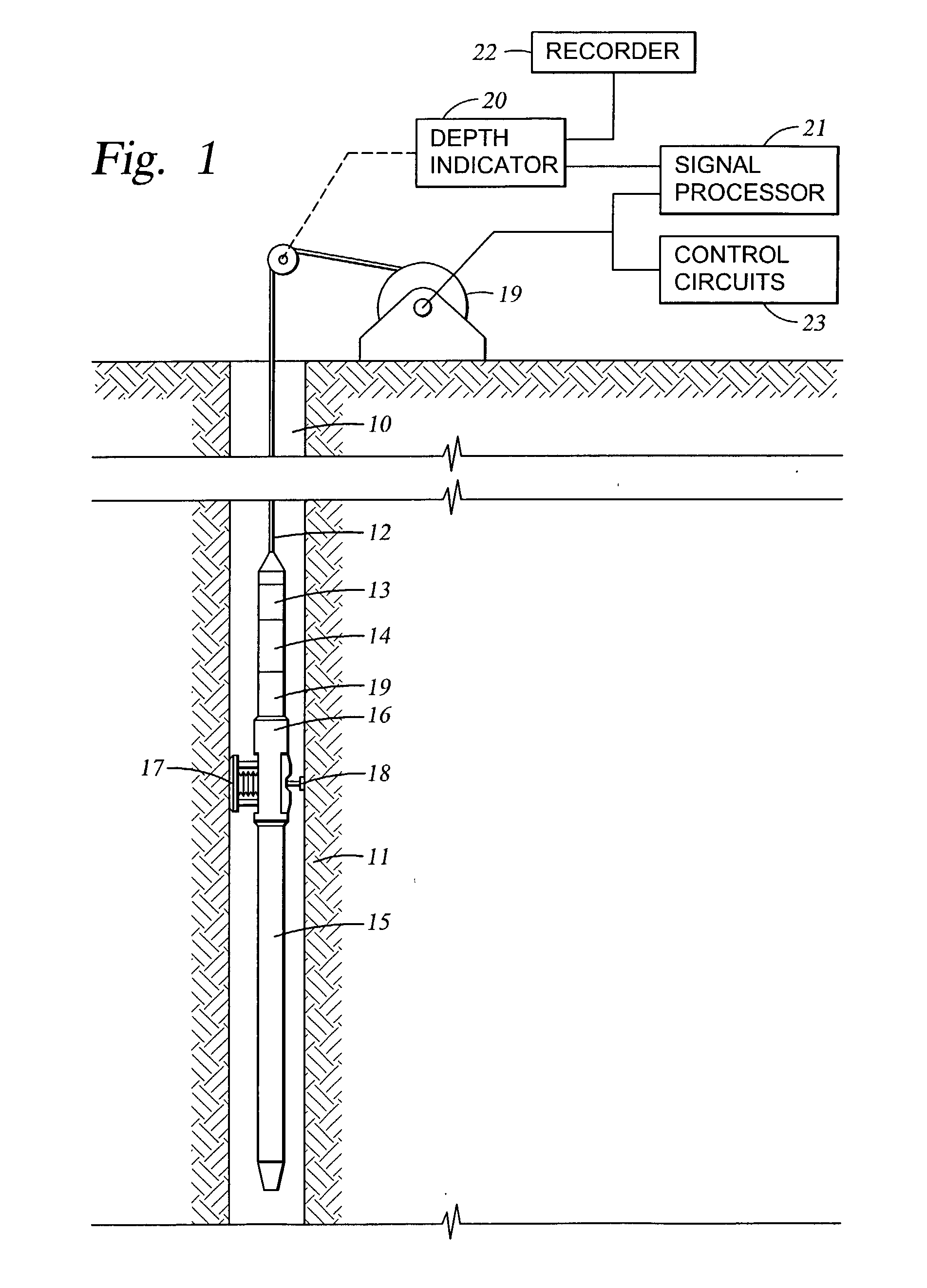
[0033] FIG. 1 is a schematic illustration of the invention in operative assembly with cooperative devices for extracting a sample of formation fluid from within a deep wellbore;

[0034] FIG. 2 is a schematic sectional view of a fundamental invention embodiment;

[0035] FIG. 3 is a schematic sectional view of one axial end of a second embodiment of the invention;

[0036] FIG. 4 is a schematic representation of the invention sample tank in the process of descending downhole.

[0037] FIG. 5 is a schematic representation of the invention sample tank receiving a formation fluid sample from the formation pump;

[0038] FIG. 6 is a schematic sectional view of the inner tubular body of the sample tank separated from the vacuum jacket;

[0039] FIG. 7 is a phase diagram for a typical hydrocarbon; and

[0040] FIG. 8 is a graph that char...


PUM


Abstract

A method and apparatus for maintaining the single phase integrity of a deep well formation sample that is removed to the surface comprises a vacuum jacket insulated single working cylinder divided by two free pistons into three variable volume chambers. The intermediate chamber is pre-charged with a fixed quantity of high pressure gas. Wellbore fluid freely admitted to one end chamber bears against one free piston to further compress the gas. The formation sample is pumped into the other end chamber to first, displace the wellbore fluid from the first end chamber and, sequentially, to further compress the gas to preserve the sample phase state upon removal to the surface.

Description

[0001] This application is related to U.S. Provisional Application No. 60 / 323,220 filed Sep. 12, 2001.[0002] 1. Field of the Invention[0003] The present invention relates to apparatus and methods for extracting representative samples of earth formation fluids. More particularly, the present invention relates to a tool for obtaining a sample of formation fluid and maintaining the sample in a single phase state until delivered to a testing laboratory.[0004] 2. Description of the Related Art[0005] The physical properties of earth formation fluids vary greatly respective to geologically diverse formations. Properties such as chemical composition, viscosity, gaseous phase envelope and solid phase envelope greatly affect the value of a formation reservoir. Further, these properties affect decisions as to whether production may be economically achieved at all and, if so, the duration, expense and unit price of such production. For these reasons, paramount importance is assigned to the accu...

Claims


Application Information

Patent Timeline
IPC IPC(8): E21B49/08E21B49/10
CPCE21B49/10
Inventor SHAMMAI, HOUMAN M.MICHAELS, JOHN M.CERNOSEK, JAMES T.MOODY, MICHAEL J.WILLS, PHILLIP
Owner BAKER HUGHES INC
Learn More