A top sealing and lubricating device for a rotary engine

A technology of rotary engine and lubricating device, which is applied to the sealing device of the engine, the lubrication of the engine, the lubricant conduit device, etc., can solve the deterioration of the seal between the top sealing sheet and the cylinder profile, the problem of lubrication is not well solved, three If the cavity cannot be completely separated, etc., it can reduce the occurrence of carbon deposits, increase the cylinder pressure, and prevent dry grinding.

Active Publication Date: 2018-06-19
上海洲跃生物科技有限公司
View PDF4 Cites 0 Cited by
  • Summary
  • Abstract
  • Description
  • Claims
  • Application Information

AI Technical Summary

Problems solved by technology

Another obvious problem with the rotary engine is that the overhaul cycle of the engine is too short. Generally, the rotary engine needs to be overhauled once when it runs for tens of thousands of kilometers, and rarely exceeds 100,000 kilometers. This is mainly due to the The space between adjacent chambers is isolated only by a top sealing sheet, which slides along the cylinder profile at high speed with the high-speed rotation of the rotor and is always in line contact with the cylinder profile. Separated, resulting in air leakage, which sharply reduces the combustion efficiency, and at the same time, the cylinder surface has scratches in the long-term friction with the top sealing sheet, which further deteriorates the seal between the top sealing sheet and the cylinder surface
Japan's Mazda Corporation has carried out decades of continuous research and development and improvement of the engine, and has done a lot of optimization work on the material, surface treatment, shape, size, etc. of the top seal, so that the performance and life of the rotary engine have a long-term improvement. Progress, however, the lubrication problem between the top seal and the cylinder profile has not been well resolved. The current lubrication method is to use a special metering oil pump to spray lubricating oil into the cylinder cavity for lubrication. Except for a small part of lubricating oil forming an oil film on the profile surface and end surface, most of the mist lubricating oil burns together with the fuel or is discharged with the exhaust gas before burning. In addition, because the top sealing plate moves in one direction, the The lubricating oil is easily scraped off by the sealing plate and it is difficult to form a stable oil film. The test shows that once the sliding surface lacks the lubricating oil film, the radial movement and resonance of the top sealing plate will easily occur, which will intensify the air leakage and deteriorate the sealing. In addition, the combustion of too much lubricating oil will inevitably lead to serious problems such as incomplete combustion and carbon deposits, which will easily cause the exhaust emission of the engine to exceed the standard; it can be seen that the lubrication condition of the contact surface between the top sealing plate and the cylinder profile is not only directly related to the performance of the engine. Life is also closely related to engine efficiency and exhaust emissions.

Method used


Image

  • A top sealing and lubricating device for a rotary engine
  • A top sealing and lubricating device for a rotary engine
  • A top sealing and lubricating device for a rotary engine

Examples


Embodiment Construction

[0021] The present invention will be further described in detail below in conjunction with the accompanying drawings and embodiments.

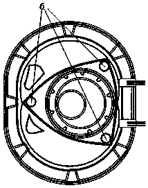
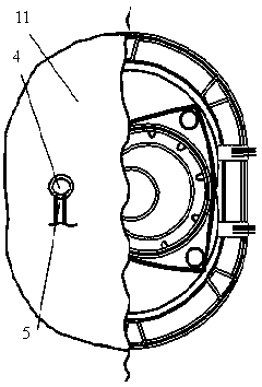
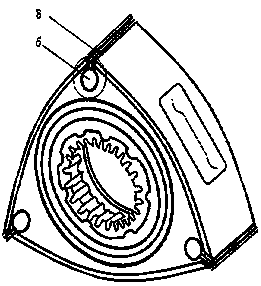
[0022] as attached Figure 1-4 The top sealing and lubricating device of a rotary engine is shown, at least consisting of a high-pressure lubricating oil pump 1, an oil delivery pipe 2, a high-pressure nozzle 3, a lubricating oil spray hole 4, an oil return pipe 5, an axial oil pipe 6, a radial oil pipe 7, and a top sealing plate 8. The corner sealing strip 9, the top sealing groove 10 and the side shell 11 are composed; the lubricating oil injection hole 4 is opened on the side shell 11 near the exhaust port of the engine, and the high-pressure nozzle 3 is installed in the lubricating oil injection hole 4; There is an oil return port in the hole 4, and the oil return port is connected with the oil return pipe 5. When the injected lubricating oil fills the axial oil pipe 6 or is blocked by the end face of the rotor due to an accident, the lubr...


PUM


Abstract

The invention discloses an upper end sealing and lubricating device for a rotary engine. The top end sealing and lubricating device at least comprises a high pressure lubricating oil pump, an oil conveying pipe, a high pressure spraying nozzle, a lubricating oil spraying hole, an oil return pipe, an axial oil pipe, a radial oil pipe, an top end sealing fin, a corner sealing strip, an top end sealing groove and a side shell. The lubricating oil spraying hole is formed in the side shell of the engine; and the high pressure spraying nozzle is installed in the lubricating oil spraying hole. The top end sealing fin comprises three sealing fins; the two sealing fins on the outer side are the rigid sealing fins; and the middle sealing fin is the flexible sealing fin. When the engine is at work, the top end sealing fin radially extrudes a profile of an air cylinder to form a sealed working face. Sucked lubricating oil is sprayed into the axial oil pipe through the high pressure spraying nozzle at high speed after being pressurized by the high pressure oil pump; and the lubricating oil enters the radial oil pipe through the centrifugal force and finally forms a continuous even lubricating oil film on the contact surface of the top end sealing fin and the profile of the air cylinder. The lubricating oil in the axial oil pipe diffuses outward into the gap between the end face of a rotor and the inner wall of the side shell from bilateral pipe mouths to be in action of lubricating a side sealing face.

Description

technical field [0001] The invention belongs to the field of engines, and relates to a rotor engine, in particular to a top sealing and lubricating device of the rotor engine. Background technique [0002] Rotary Engine was invented by German Felix Wankel (Felix Wankel, 1902-1988), so it is also called Wankel Engine. The rotary engine uses the rotary motion of the triangular rotor to complete the suction, compression, work, and exhaust strokes, which is quite different from the linear motion of the traditional reciprocating piston engine. The rotor of the rotary engine expands and does work three times every time it rotates, while the general four-stroke engine only works once every two circles, so the rotor engine has a high power-to-volume ratio. In addition, the unique axial motion of the rotary engine allows it to reach high speeds without the need for precise crankshaft balancing. The whole engine has only two rotating parts, which saves more than 20 moving parts such...

Claims


Application Information

Patent Timeline
Patent Type & Authority Patents(China)
IPC IPC(8): F02F11/00F01M1/08F01M11/02
CPCF01M1/08F01M11/02F01M2001/083F01M2011/022F02F11/007
Inventor 李春洲
Owner 上海洲跃生物科技有限公司
Why Eureka
Try Eureka