Refrigeration device

a refrigeration device and compressor technology, applied in the field of refrigeration devices, can solve the problems of affecting the efficiency the complexity of the compressor of the so-called refrigeration device is significantly increased, and the control of the possible fine is not free from drawbacks, so as to increase the efficiency of the refrigeration device, the effect of increasing the complexity of the refrigeration devi

Active Publication Date: 2018-12-04
ANGELANTONI TEST TECH
View PDF7 Cites 0 Cited by
  • Summary
  • Abstract
  • Description
  • Claims
  • Application Information

AI Technical Summary

Benefits of technology

[0012]Object of the present invention is, therefore, to increase the efficiency of the refrigeration devices operating with reciprocating compressor, without neither increasing the complexity of the refrigeration device nor that one of the reciprocating compressor operating inside the refrigeration device.
[0013]Further object of the invention is to increase the refrigeration load of the refrigeration device according to the invention, the displacement of the reciprocating compressor operating in known refrigeration devices being equal.
[0015]The Owner has in fact tested that the entrance of a first fraction of flow rate from a secondary economizer branch through a first port placed on the compressor cylinder, at an inlet pressure higher than the suction pressure and, however, not higher than 4 bar with respect to the latter, and preferably lower than 2 bar, allows reaching multiple results. In fact, thanks to this solution the efficiency of the refrigeration cycle becomes greatly increased with respect to a refrigeration cycle working at the same operating conditions, i.e. same pressures, temperatures and same coolant. In addition, such a solution also allows greatly increasing the refrigeration load, the displacement of the employed reciprocating compressor being the same. This is mainly due to the fact that, when the pressure of said at least one first fraction of flow rate of coolant from the first secondary economizer branch is reduced, a remarkable increase of the volumetric flow rate is obtained that, consequently, greatly increases the cylinder pressure when enters the compressor through said first port, thus resulting in a reduction of the compression work done by the compressor. Such a reduction of compressor work leads to a remarkable increase of the efficiency of the whole refrigeration device.
[0017]In practice, the more the inlet port will be close to the bottom dead centre of the piston, the less will be the work of the piston in its inlet and compression steps. In addition, the more the inlet port will be close to the bottom dead centre of the piston, the less will be the loss of piston stroke in the period of time the side port remains exposed. Therefore, such a solution allows maximizing the efficiency of the refrigeration device according to the invention.

Problems solved by technology

However, such a refrigeration device is not free from drawbacks.
In fact, the possible and alleged fine obtained control occurs to the detriment of the efficiency possibly reached by using a secondary economizer branch.
In addition, a so-made refrigeration device involves however a significant increase of the same compressor complexity since the piston motion speed has always to be driven as a function of one or more external parameters.
On the other hand it has to be noted that for the other commercially available coolants the result would have probably been different, but the deviation from the aforementioned value absolutely poorly significant.

Method used


Image

  • Refrigeration device
  • Refrigeration device
  • Refrigeration device

Examples


Embodiment Construction

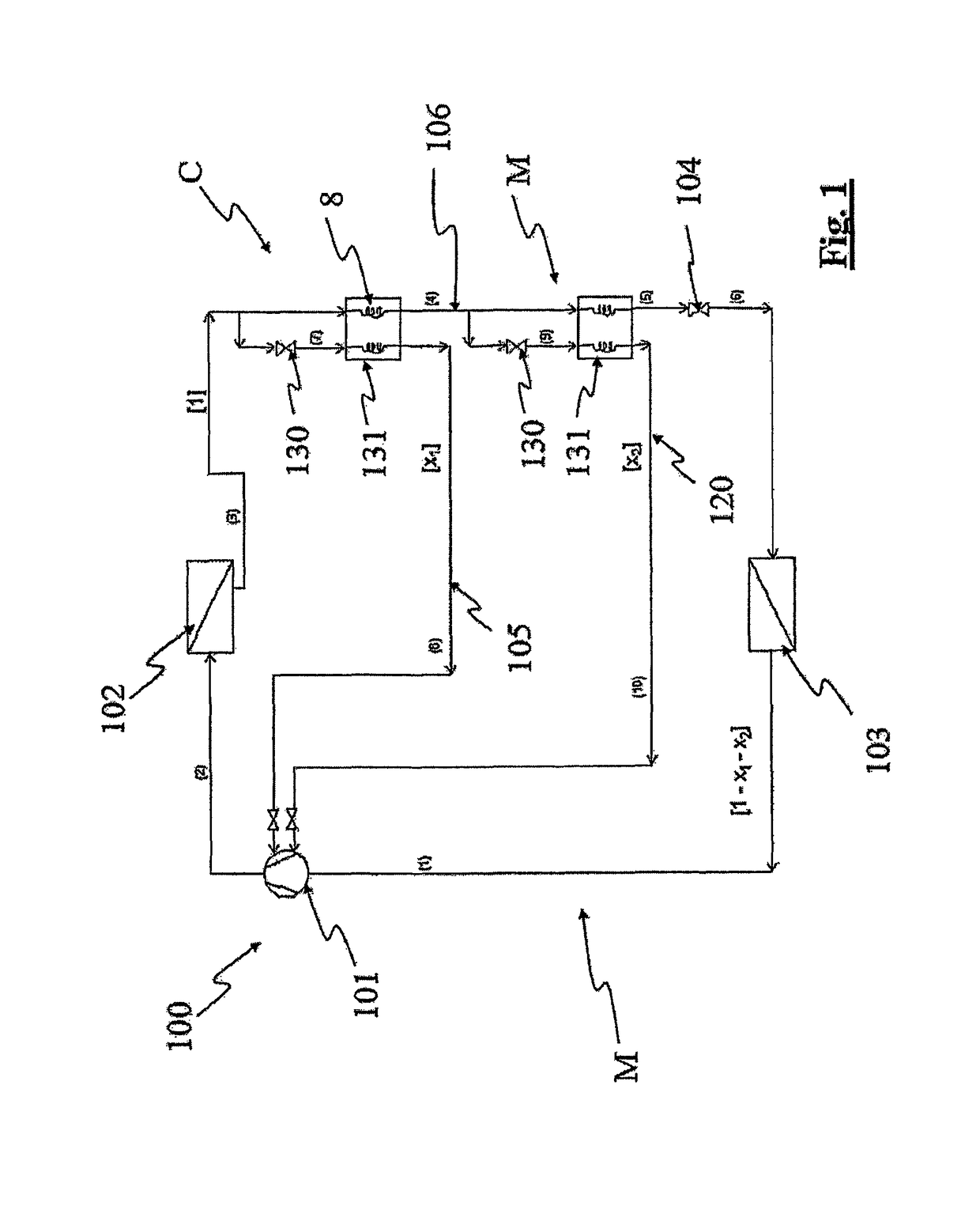
[0033]Referring in particular to such figures, the generic refrigeration device according to the invention has been denoted with numeral 100.

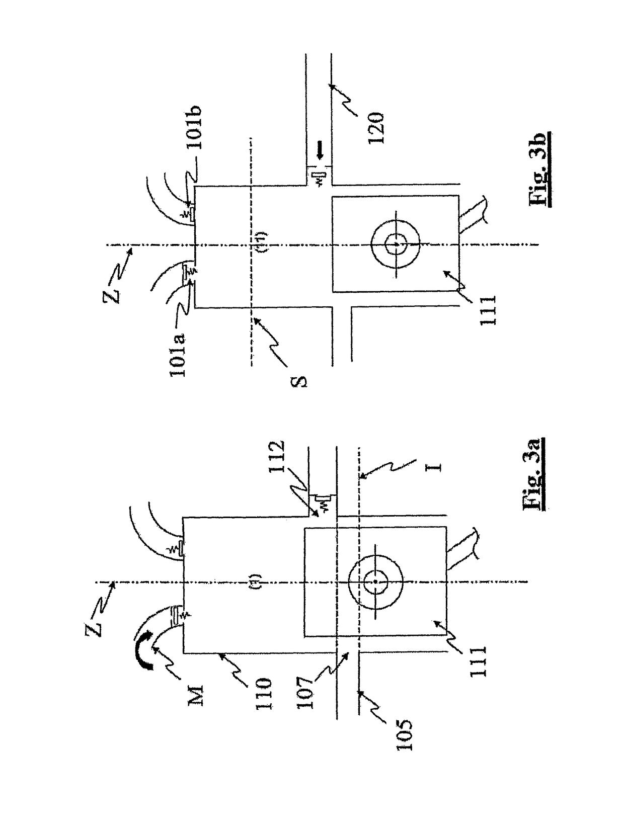
[0034]The refrigeration device 100 comprises a closed circuit C in which a flow rate of coolant 1 is circulating. Such a closed circuit C comprises a condenser 102 and a main branch M having a reciprocating compressor 101 provided with a cylinder 110 and a piston 111 reciprocatingly moving inside the cylinder 110, between a top dead centre S (see FIG. 3d) and a bottom dead centre I (see FIG. 3c), and inside which a defined flow rate 1−X1−X2 of the coolant enters, from said main branch M, at a defined suction pressure P1. Such a main branch M is further provided with an evaporator 103 and a first expansion valve 104 arranged between the condenser 102 and the evaporator 103. Such a closed circuit C comprises, in addition, a first secondary economizer branch 105 for a first fraction of flow rate X1 of the coolant. Such a first secondary economizer...


PUM


Abstract

A refrigeration device having a closed circuit in which a flow rate of coolant is circulating is provided. The closed circuit has a condenser and a main branch provided with a reciprocating compressor inside which a defined flow rate of the coolant enters, from the main branch, at a defined suction pressure, of an evaporator and a first expansion valve that is arranged between the condenser and the evaporator. The closed circuit further has a first secondary economizer branch for a first fraction of flow rate of the coolant, the first secondary economizer branch fluidically connecting the compressor to a section of the closed circuit between the condenser and the first expansion valve, wherein the compressor has a first side inlet port for the entrance of the first fraction of coolant flow rate.

Description

CROSS-REFERENCE TO RELATED APPLICATIONS[0001]This application is a 371 of PCT / IB2015 / 059532 filed Dec. 11, 2015, which claims the benefit of Italian Patent Application No. PG2014000063 filed Dec. 11, 2014.FIELD OF THE INVENTION[0002]The present invention relates to a refrigeration device.KNOWN PREVIOUS ART[0003]In particular, the refrigeration device according to the invention is advantageously used in case the closed circuit, in which the coolant flows, comprises in addition to the condenser, the expansion valve and the evaporator, also a reciprocating compressor and a secondary economizer branch for the coolant circulating in the same closed circuit. It has to be noted that, according to known art, such a secondary branch is fluidically connected to a section of the main branch of the closed circuit comprised between the condenser and the expansion valve, on the one hand, and to the cylinder of the reciprocating compressor for the re-injection, into the compressor itself, of the f...

Claims


Application Information

Patent Timeline
Patent Type & Authority Patents(United States)
IPC IPC(8): F25B1/02F25B41/06
CPCF25B1/02F25B41/062F25B2400/13F25B2400/0409F25B2341/0661F25B41/385
Inventor ASCANI, MAURIZIO
Owner ANGELANTONI TEST TECH
Why Eureka
Try Eureka