
Method and apparatus for location area updating in cellular communications

a technology of cellular communication and location area, applied in the direction of electrical apparatus, wireless communication services, wireless communication services, etc., can solve the problems of high paging cost, low paging cost, and tension in the network mobility process, so as to reduce or eliminate unnecessary involvement of the core network, minimize the amount of location area update signaling, and minimize the effect of signaling overhead

Inactive Publication Date: 2003-02-27
TELEFON AB LM ERICSSON (PUBL)
View PDF10 Cites 134 Cited by
  • Summary
  • Abstract
  • Description
  • Claims
  • Application Information

AI Technical Summary

Benefits of technology

[0005] In W-CDMA technology, a common frequency band allows simultaneous communication between a user equipment unit and plural base stations. Signals occupying the common frequency band are discriminated at the receiving station through spread spectrum CDMA waveform properties based on the use of a high speed, pseudo-noise (PN) code. These high speed PN codes are used to modulate signals transmitted from the base stations and the user equipment units. Transmitter stations using different PN codes (or a PN code offset in time) produce signals that can be separately demodulated at a receiving station. The high speed PN modulation also allows the receiving station to advantageously generate a received signal from a single transmitting station by combining several distinct propagation paths of the transmitted signal. In CDMA, therefore, a user equipment unit need not switch frequency when handoff of a connection is made from one cell to another. As a result, a destination cell can support a connection to a user equipment unit at the same time the origination cell continues to service the connection. Since the user equipment is always communicating through at least one cell during handover, there is no disruption to the call. Hence, the term "soft handover." In contrast to hard handover, soft handover is a "make-before-break" switching operation.
[0007] Mobility features of a mobile radio communications system can be divided into two areas: radio mobility, which mainly consists of handover, and network mobility, which mainly consists of location management including location updating and paging. The present invention relates to network mobility. There is a tension in the network mobility process between location and paging procedures. The location procedure allows the system to monitor a user equipment's location in order to be able to find that user in case of an incoming call. Location registration is also used to bring the user's service profile near its location and allows the network to provide the services for which the user has subscribed. The paging process sends paging messages to cells where the mobile terminal could be located. Therefore, if the location cost is high, meaning that the user's location knowledge is accurate, the paging cost will be low, and paging messages need only be transmitted to a small number of cells. On the other hand, if the location cost is low, the paging cost will be high, and paging messages will have to be transmitted over a wider area.
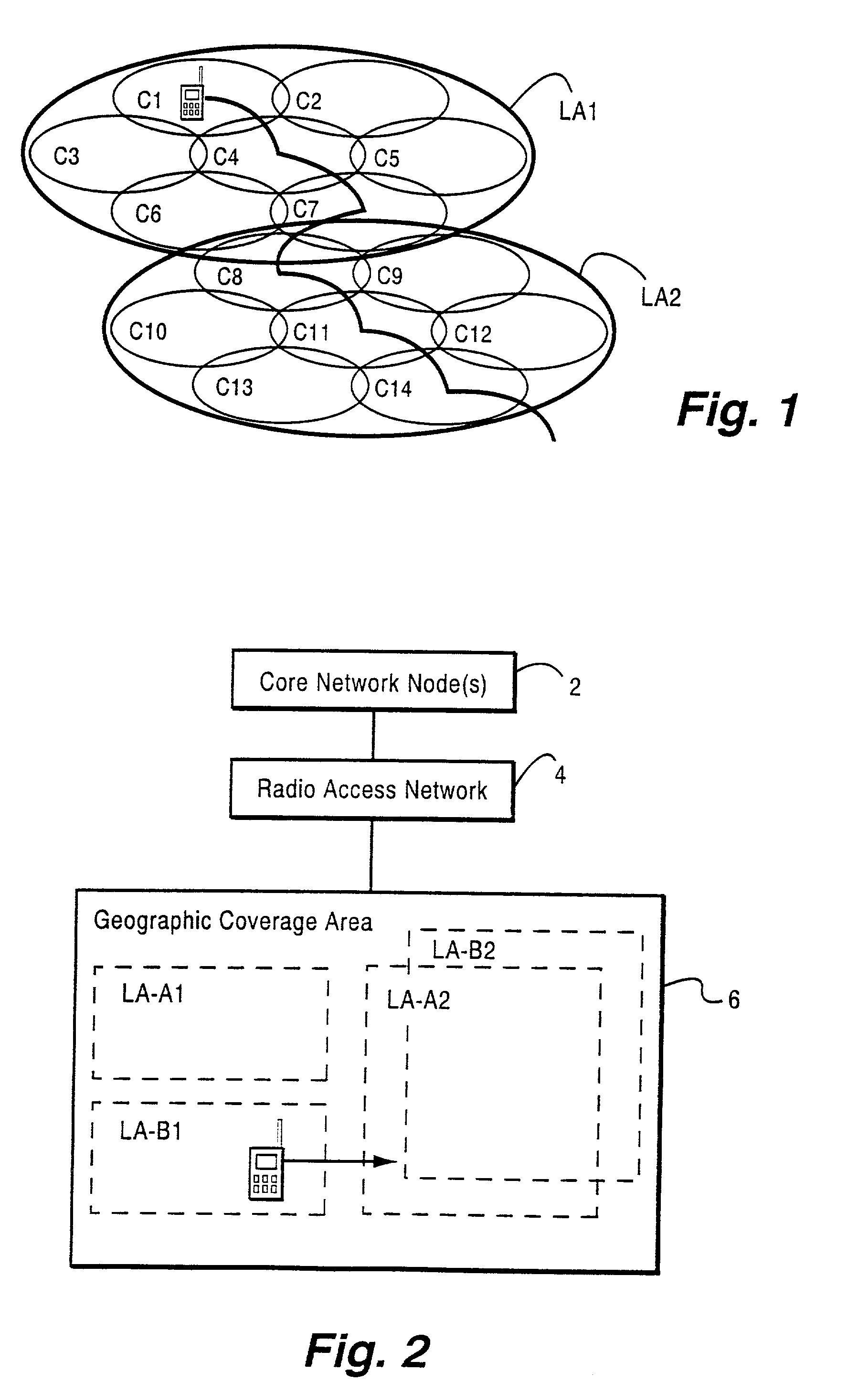
[0009] Location area signaling overhead is particularly problematic in shared network situations. A shared network is a radio access network infrastructure shared by two or more cellular operators, typically to reduce the cost of network buildout and maintenance. FIG. 2 illustrates an example shared network 1 and includes a core network with one or more core network nodes 2 coupled to a radio access network (RAN) 4 which provides radio access service to a geographic coverage area 6. The core network typically has some significant responsibilities in handling mobile terminal registrations, location area monitoring and updates, and paging.
[0030] The present invention may be employed in any cellular communications system including for example that shown in FIG. 2 as well as the UMTS system shown in FIG. 6 and described below. One objective of the present invention is to maintain control of the mobility management type functions in the non-access stratum (NAS). Another objective of the present invention is to provide location area update procedures for connected mobile terminals, where necessary, while at the same time minimizing the amount of location area update signaling required.
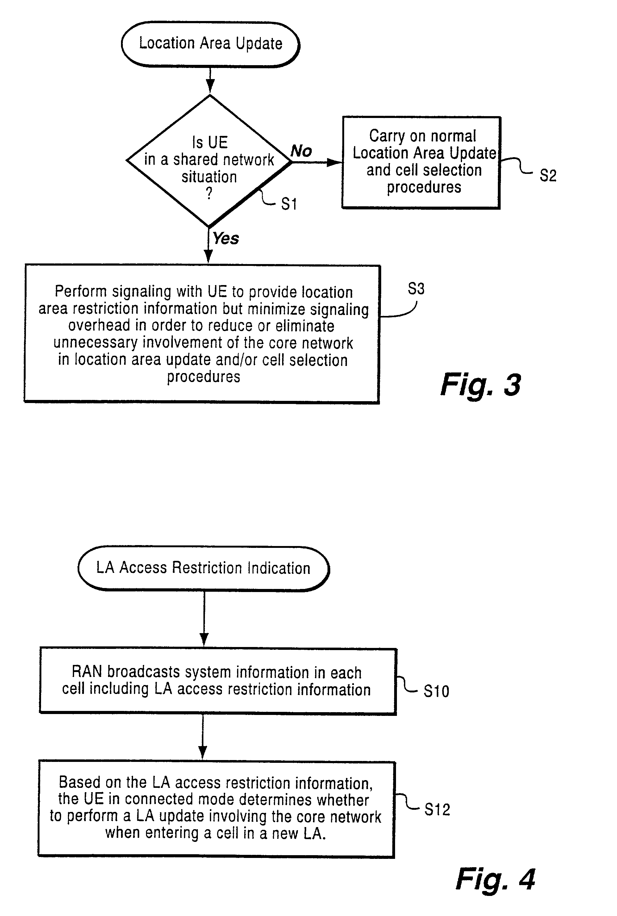
[0031] One example, non-limiting situation where such location area update procedures may be necessary is in a shared network. In this regard, reference is made to the location area update procedure illustrated in flowchart form in FIG. 3. A decision is made in step S1 whether the mobile terminal user equipment is in a shared network situation. If not, the user equipment and the cellular system carry on normal location area update and cell selection procedures as shown in step S2. However, in a shared network situation, signaling is performed with the UE to provide location area access restriction information with minimum signaling overhead in order to reduce or eliminate unnecessary involvement of the core network in location area update and / or cell selection procedures.

Problems solved by technology

There is a tension in the network mobility process between location and paging procedures.
Therefore, if the location cost is high, meaning that the user's location knowledge is accurate, the paging cost will be low, and paging messages need only be transmitted to a small number of cells.
On the other hand, if the location cost is low, the paging cost will be high, and paging messages will have to be transmitted over a wider area.
However, a problem with location area procedures is the associated signaling overhead.
Location area signaling overhead is particularly problematic in shared network situations.
The difficulty with this comprehensive location area update approach for idle and connected mobiles is that it adds substantial location area signaling load / overhead, and in particular, when the network is not shared between different operators.
However, there may be circumstances that do not relate to network mobility where it is desired to have a location area update procedure be selectively performed by a mobile terminal operating in connected mode, e.g., in a shared network scenario as described above.

Method used


Image

  • Method and apparatus for location area updating in cellular communications
  • Method and apparatus for location area updating in cellular communications
  • Method and apparatus for location area updating in cellular communications

Examples


Embodiment Construction

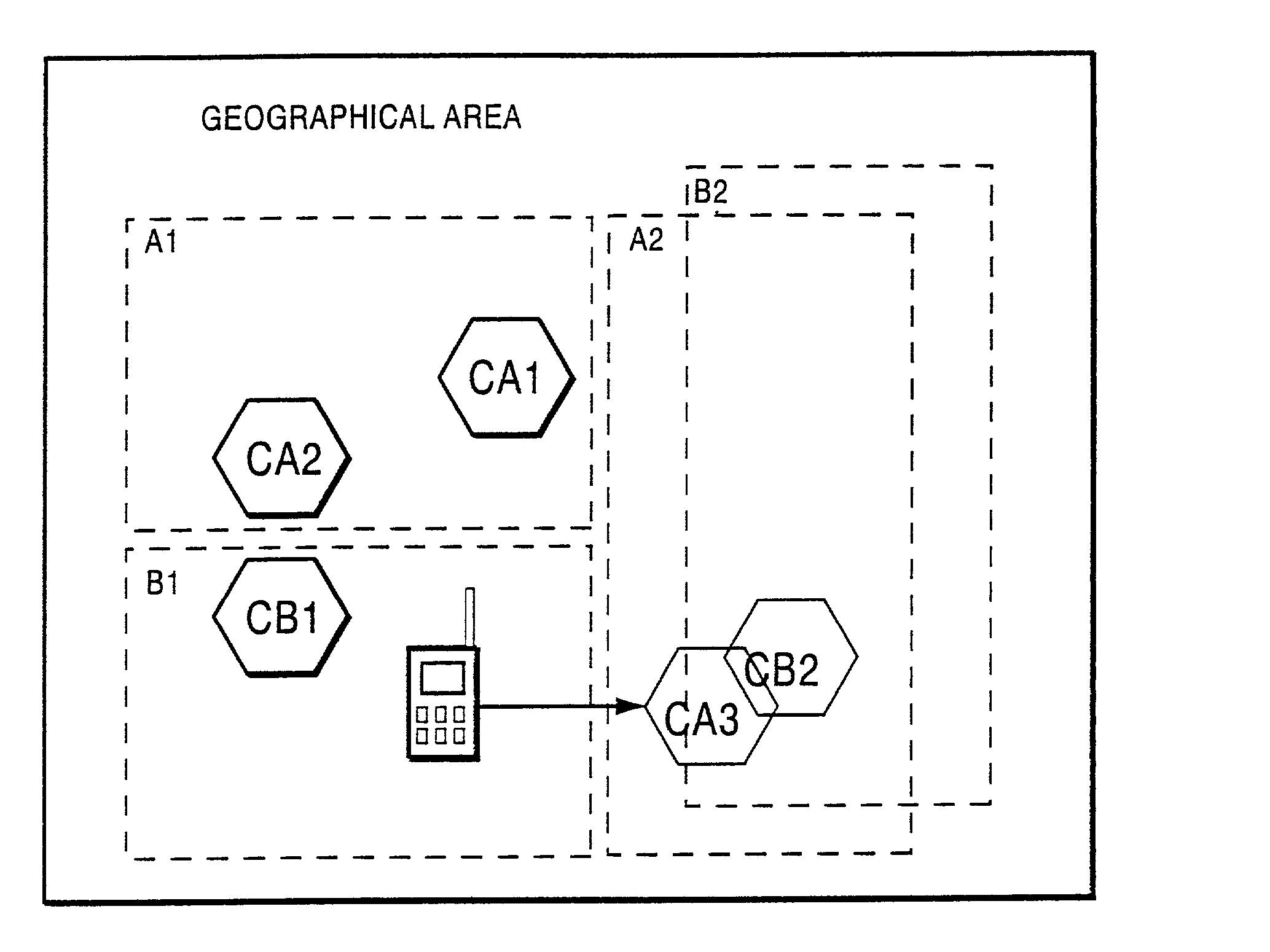
message that includes a location area ID for that location area and an access restriction indication. The message is transmitted via the base station over a broadcast channel for the new cell being considered for selection by the mobile radio terminal. The mobile terminal checks that SYSTEM INFORMATION message to determine if the cell is in a new location area. If not, no further location area update is necessary. However, if the cell is in a new location area, the mobile terminal examines the address restriction indicator (ARI) in the SYSTEM INFORMATION message. If it is not set (false), the mobile user equipment terminal does not send a location update request to the core network. On the other hand, if the ARI is set (true), the radio terminal sends a LOCATION UPDATING REQUEST message to the core network. From that message, the core network detects the mobile terminal's IMSI and determines whether it is permitted in the new location area, e.g., by comparing it to a list of mobile ...


PUM


Abstract

A connection is established between a mobile radio terminal and a radio access network serving plural geographic coverage areas. The radio access network transmits information associated with one of the geographic coverage areas indicating whether the one geographic coverage area requires a geographic coverage area update procedure. During the connection, when the mobile radio terminal considers selecting the one geographic coverage area, it determines whether to perform a geographic coverage area update procedure depending on the transmitted information associated with the one geographic coverage area. In a preferred, non-limiting application, the radio access network is shared by two operators, and the transmitted information indicates that the geographic coverage area update procedure should be performed for geographic coverage areas that are shared by the two operators and that the geographic coverage area update procedure need not be performed for geographic coverage areas that are not shared by the two operators.

Description

[0001] The present invention relates generally to location area updating in cellular radio telecommunications, and in one particular application, to location area updating in situations where a radio access network is shared by two or more operators.BACKGROUND AND SUMMARY[0002] In a typical cellular radio system, "wireless" user equipment units (UEs) and one or more "core" networks like the public telephone network or Internet) communicate via a radio access network (RAN). The UEs very often are mobile, e.g., cellular telephones and laptops with mobile radio communication capabilities (mobile terminals). UEs and the core networks communicate both voice and data information via the radio access network.[0003] The radio access network services a geographical area which is divided into cell areas, with each cell area being served by a base station (BS). Thus, a base station can serve one or multiple cells. A cell is a geographical area where radio coverage is provided by the radio base...

Claims


Application Information

Patent Timeline
Patent Type & Authority Applications(United States)
IPC IPC(8): H04W48/10H04W48/12H04W48/14H04W48/18H04W60/00H04W60/04H04W92/02
CPCH04W48/10H04W48/12H04W48/14H04W48/18H04W60/00H04W60/04H04W92/02
Inventor HOGAN, WILLIAM DAMIANOSTRUP, NILS PETER
Owner TELEFON AB LM ERICSSON (PUBL)
Learn More