
Variable transmission rate services in a radio access network

Inactive Publication Date: 2005-05-03
INTERDIGITAL PATENT HLDG INC
View PDF11 Cites 168 Cited by
  • Summary
  • Abstract
  • Description
  • Claims
  • Application Information

AI Technical Summary

Benefits of technology

[0005]In W-CDMA technology, a common frequency band allows simultaneous communication between a user equipment unit and plural base stations. Signals occupying the common frequency band are discriminated at the receiving station through spread spectrum CDMA waveform properties based on the use of a high speed, pseudo-noise (PN) code. These high speed PN codes are used to modulate signals transmitted from the base stations and the user equipment units. Transmitter stations using different PN codes (or a PN code offset in time) produce signals that can be separately demodulated at a receiving station. The high speed PN modulation also allows the receiving station to advantageously generate a received signal from a single transmitting station by combining several distinct propagation paths of the transmitted signal. In CDMA, therefore, a user equipment unit need not switch frequency when handoff of a connection is made from one cell to another. As a result, a destination cell can support a connection to a user equipment unit at the same time the origination cell continues to service the connection. Since the user equipment is always communicating through at least one cell during handover, there is no disruption to the call. Hence, the term “soft handover.” In contrast to hard handover, soft handover is a “make-before-break” switching operation.
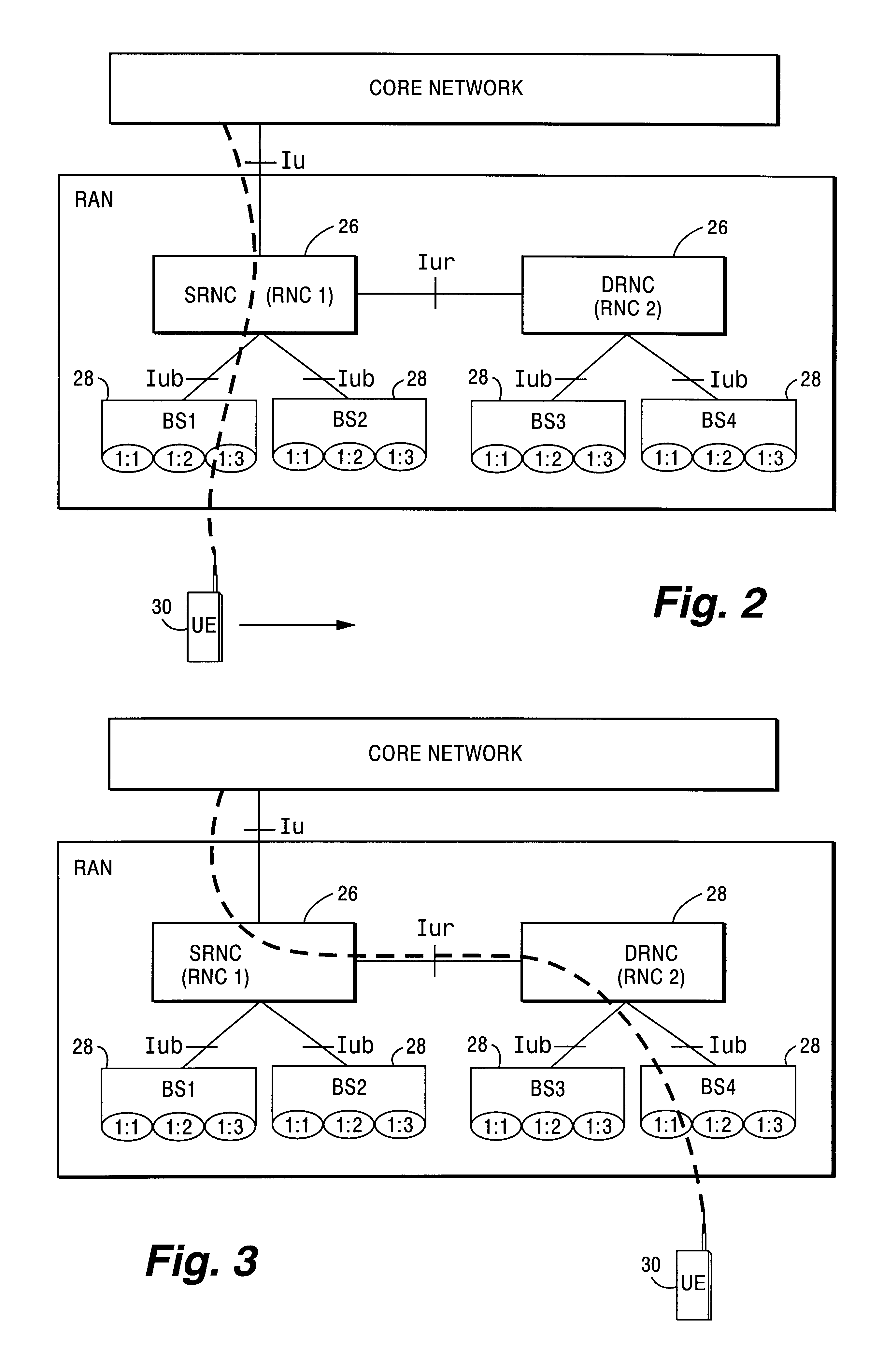
[0015]As a result, there are inefficiencies in allocating dedicated channel resources over the Iur interface. Because the drift RNC must reserve resources for the maximum possible rate of the dedicated channel, some of the reserved radio bandwidth is not used because the serving RNC is not transmitting at the maximum rate. Precious bandwidth is wasted. It is a primary object of the present invention to avoid this inefficiency and thereby increase the capacity of the radio access network.

Problems solved by technology

However, the drift RNC does not give the serving RNC any guarantees on the transmission rate / throughput for a connection mapped to a common transport channel.
As a result, there are inefficiencies in allocating dedicated channel resources over the Iur interface.
Precious bandwidth is wasted.
Unfortunately, it is difficult to define average bit rate.
Such a model is complicated and difficult to provide.
Moreover, the drift RNC and / or base station cannot in that case request that a bit rate be used that is lower than the guaranteed bit rate.

Method used


Image

  • Variable transmission rate services in a radio access network
  • Variable transmission rate services in a radio access network
  • Variable transmission rate services in a radio access network

Examples


Embodiment Construction

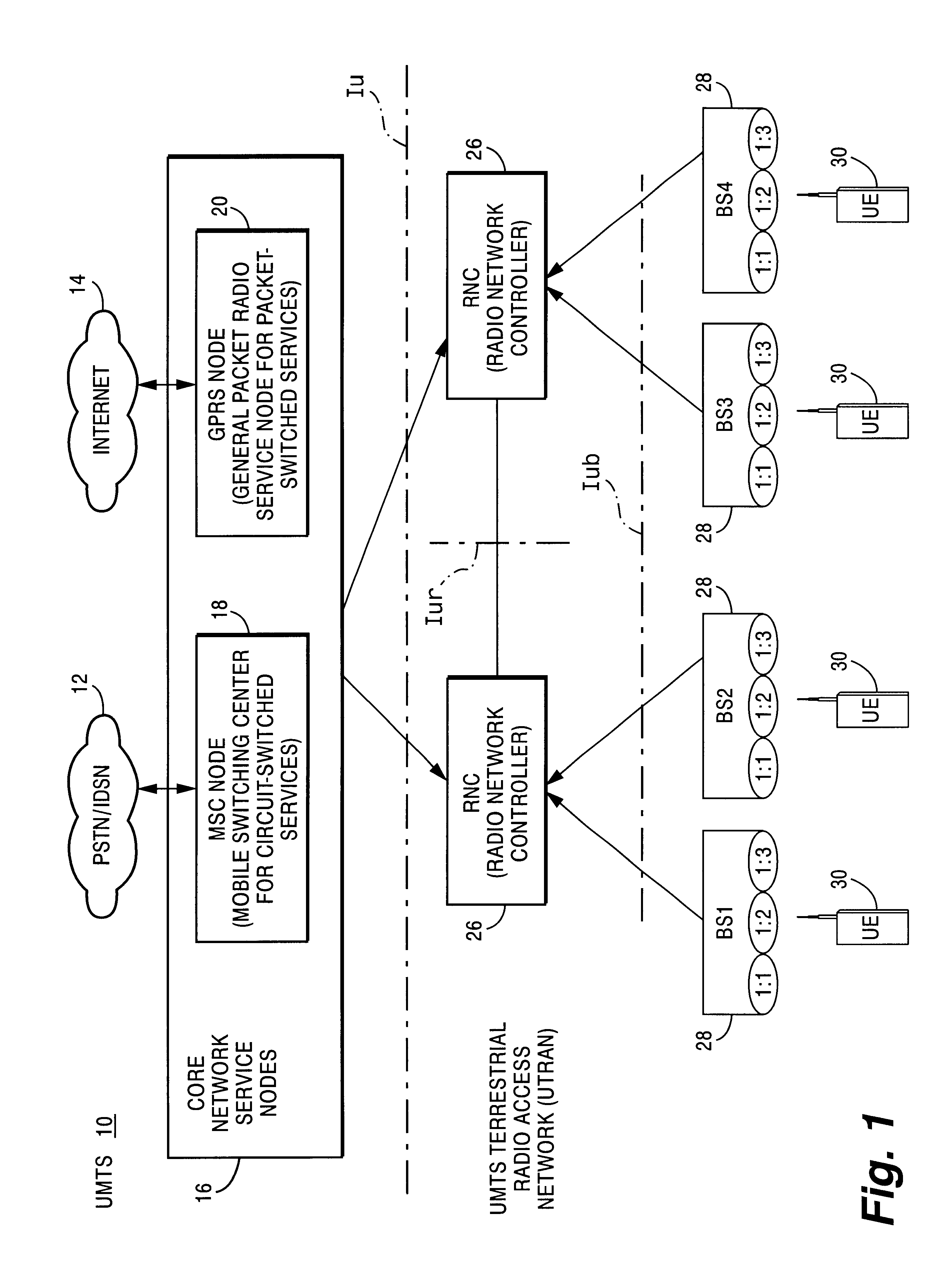
[0030]In the following description, for purposes of explanation and not limitation, specific details are set forth, such as particular embodiments, procedures, techniques, etc. in order to provide a thorough understanding of the present invention. However, it will be apparent to one skilled in the art that the present invention may be practiced in other embodiments that depart from these specific details. For example, while the present invention is described in the context of rate control between particular nodes in the RAN, e.g., a serving RNC and a drift RNC, the present invention may be employed for rate control between any nodes in a radio access network in either or both uplink and downlink directions.

[0031]In some instances, detailed descriptions of well-known methods, interfaces, devices, and signaling techniques are omitted so as not to obscure the description of the present invention with unnecessary detail. Moreover, individual function blocks are shown in some of the figu...


PUM


Abstract

A connection is supported in a radio access network (RAN) between an external network to a UE using a first RAN node and second RAN node. The transmission rate from the first RAN node to the second RAN node is regulated based on a rate control request from the second RAN node. In one example embodiment, the first and second RAN nodes correspond to a serving radio network controller and a drift radio network controller, respectively. In another example embodiment, the first and second RAN nodes correspond to a radio network controller and radio base station, respectively. The rate control request is made based upon a congestion or load condition being monitored by the second RAN node. When the load condition is detected, the second RAN node requests the first RAN node to lower the transmission rate of information. Conversely, when the load condition is relieved, the second RAN node can request that the first RAN node increase the transmission rate of information. The rate control may be applied in both downlink and uplink directions.

Description

FIELD OF THE INVENTION[0001]The present invention relates to telecommunications, and particularly, to handling variable transmission rate services in a radio access network.BACKGROUND AND SUMMARY[0002]In a typical cellular radio system, “wirelessuser equipment units (UEs) and one or more “core” networks (like the public telephone network or Internet) communicate via a radio access network (RAN). The UEs very often are mobile, e.g., cellular telephones and laptops with mobile radio communication capabilities (mobile terminals). UEs and the core networks communicate both voice and data information via the radio access network.[0003]The radio access network services a geographical area which is divided into cell areas, with each cell area being served by a base station (BS). Thus, a base station can serve one or multiple cells. A cell is a geographical area where radio coverage is provided by the radio base station equipment at a base station site. Each cell is identified by a unique...

Claims


Application Information

Patent Timeline
IPC IPC(8): H04Q7/38H04L12/56H04W28/22H04W36/12
CPCH04L47/10H04L47/12H04W36/12H04L47/25H04W28/22H04L47/14H04W28/0247H04W28/0289H04W8/04
Inventor WILLARS, PERRUNE, GORAN
Owner INTERDIGITAL PATENT HLDG INC
Learn More