
Hydrocarbon gas processing

a technology of hydrocarbon gas and processing method, which is applied in the direction of cold treatment separation, liquefaction, solidification, etc., can solve the problems of not only the capital cost of the plant, but also the operating expense of the plant, and the substantial incremental cost of operating in this manner

Inactive Publication Date: 2003-02-13
TREBBLE MARK A
View PDF0 Cites 49 Cited by
  • Summary
  • Abstract
  • Description
  • Claims
  • Application Information

AI Technical Summary

Benefits of technology

[0007] In a typical cryogenic expansion recovery process, the bottom stream from the demethanizer is typically sent for fractionation in a deethanizer where the ethane (C2), carbon dioxide and lighter components are separated from the propane and heavier (C3+) components. The overhead of the deethanizer is typically configured with a condenser which takes all of the C2, carbon dioxide and lighter components as a vapor from the deethanizer and completely condenses it to make a liquid product comprising primarily of C2 and smaller amounts of carbon dioxide and lighter components. The current invention does not condense all the vapour leaving the deethanizer overhead but a portion of the vapour is recycled back to an upstream point, typically directly into an upper portion of the demethanizer column. This recycle vapor stream is always richer in methane and carbon dioxide than the liquid ethane product stream, which allows the liquid ethane product stream to be lower in carbon dioxide and methane even though the liquid stream leaving the bottom of the demethanizer may have excessive amounts of methane and carbon dioxide. The amount of vapor recycle is directly controllable by raising or lowering the cooling to the overhead stream from the deethanizer thereby controlling the degree of condensing of the vapor stream leaving the deethanizer.

Problems solved by technology

There are many options for removing the carbon dioxide (treating the incoming feed gas, treating the total liquid product, treating the ethane product after fractionation, etc.), but all of these options will add not only to the capital cost of the plant due to the cost of installing the treating system, but also to the operating expense of the plant due to energy and / or chemical consumption in the treating system.
This preheating requires an addition of 17,900,000 Btu / hr in exchanger E413 which represents a substantial incremental cost of operating in this manner.
It is clear from Table 2 that meeting the required CO2 content has a disastrous effect on the recovery of ethane.
Second, the higher temperatures in the top of the demethanizer results in less available cooling for the reflux stream (5) so that the temperature of the inlet reflux stream to the demethanizer (19) increases from 155.degree. F. to 153.degree. F.
This effectively means that substantially less liquids are available for reflux in the FIG. 2 process, which also results in a lower ethane recovery in the demethanizer.

Method used


Image

  • Hydrocarbon gas processing
  • Hydrocarbon gas processing
  • Hydrocarbon gas processing

Examples


Embodiment Construction

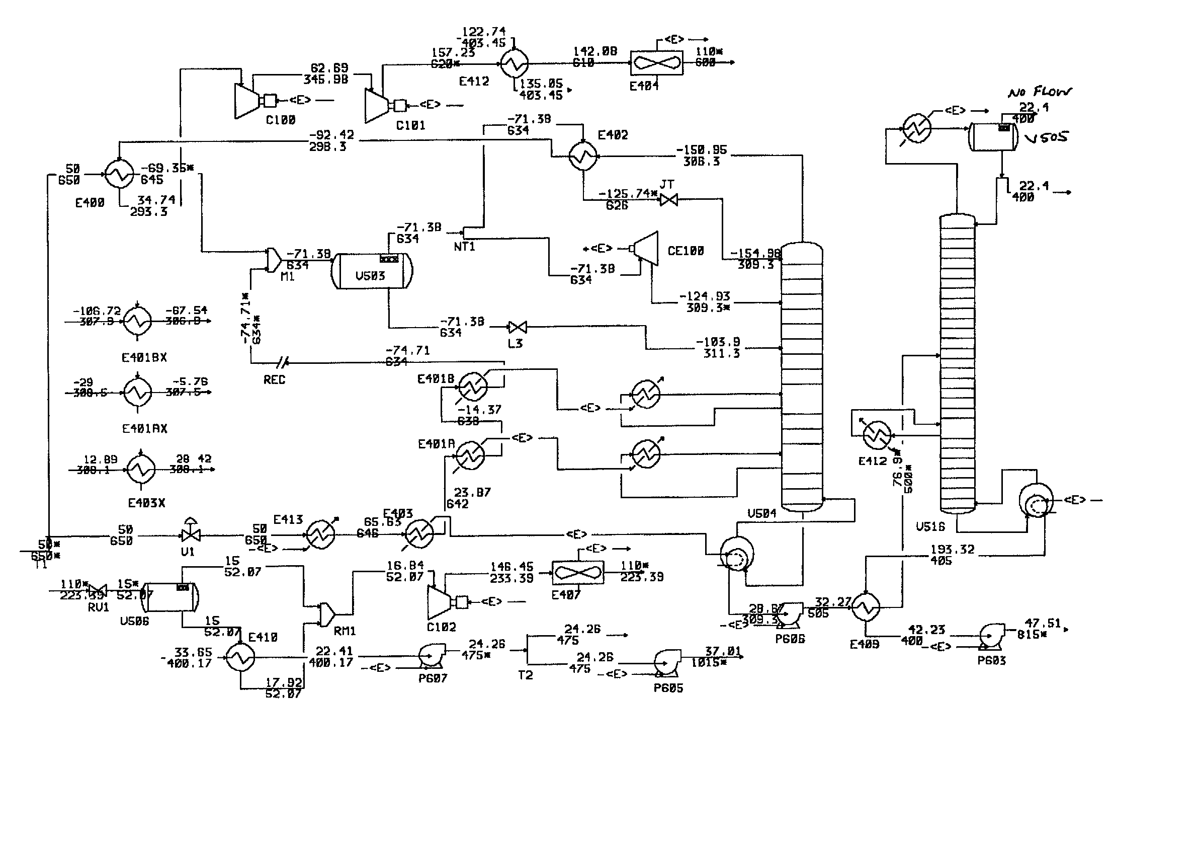
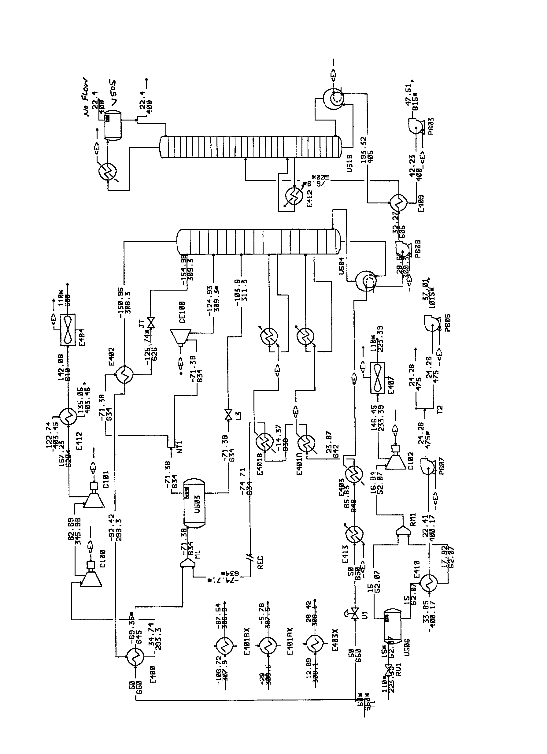
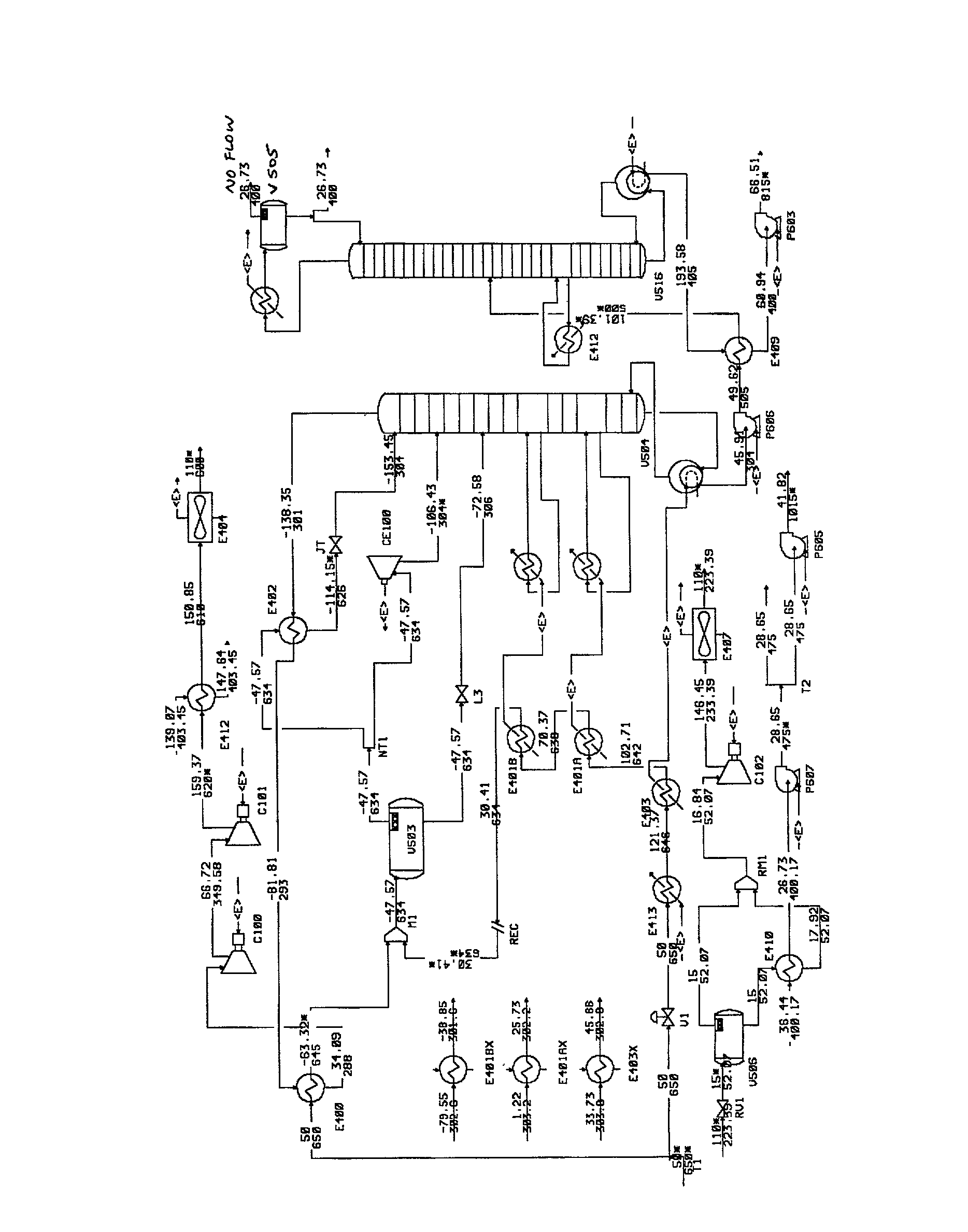
. 3 and 4 illustrate flow diagrams of a process in accordance with the present invention. The feed gas composition and conditions considered in the inventive process are the same as those in prior art FIGS. 1 and 2 and comprises a similar cryogenic expansion recovery process. Accordingly, the FIGS. 3 / 4 process can be compared with that of the FIGS. 1 and 2 processes to illustrate the operation of the present invention. The FIGS. 3 / 4 process described below is exemplary of the present invention and is not intended to limit the invention claimed herein. In particular, one skilled in the art will realize that many variations on the demethanizer deethanizer configuration and the various energy exchanges illustrated exist which are compatible with and included within the scope of the claimed invention. In the simulation of the FIG. 3 process, inlet gas (stream 1) enters at 50.degree. F. and a pressure of 650 psia. The feed stream 1 is split into streams 2 and 3. Stream 2 is subsequently ...


PUM


Abstract

A cryogenic natural gas liquids recovery process which includes the use of a demethanizer and a deethanizer includes a step of recycling a portion of the deethanizer overhead to the demethanizer.

Description

BACKGROUND OF INVENTION[0001] The present invention relates to methods of processing hydrocarbon gases. In particular, it relates to methods of limiting the carbon dioxide content of liquids produced from natural gas liquids recovery processes.[0002] Ethylene, ethane, propylene, propane and / or heavier hydrocarbons can be recovered from a variety of gases, such as natural gas, refinery gas, and synthetic gas streams obtained from other hydrocarbon materials such as coal, crude oil, naphtha, oil shale, tar sands, and lignite.[0003] Natural gas usually has a major proportion of methane and ethane, usually in excess of 50 mole percent of the gas. The gas also contains relatively lesser amounts of heavier hydrocarbons such as propane, butanes, pentanes and the like, as well as hydrogen, nitrogen, carbon dioxide and other gases. The present invention is generally concerned with the recovery of ethylene, ethane, propylene, propane and heavier hydrocarbons from such gas streams. A typical a...

Claims


Application Information

Patent Timeline
IPC IPC(8): F25J3/02
CPCF25J3/0209F25J3/0233F25J3/0238F25J3/0242F25J2200/02F25J2200/04F25J2200/70F25J2200/72F25J2200/74F25J2205/04F25J2215/62F25J2240/02F25J2245/02Y02C10/12Y02C20/40
Inventor TREBBLE, MARK A.
Owner TREBBLE MARK A
Learn More