Method of treating metal analysis sample and device thereof

a metal analysis and apparatus technology, applied in the direction of checking devices, heat treatment process control, blast furnaces, etc., can solve the problems of significant error in analytical value, complicated operation of reversing the sample, and contaminated surface of the analytical metal sample with cleaning and polishing chemicals, etc., to achieve the effect of effectively removing (sputtering) surface contaminants

Inactive Publication Date: 2003-01-16
JAPAN ANALYST CORP +3
View PDF0 Cites 16 Cited by
  • Summary
  • Abstract
  • Description
  • Claims
  • Application Information

AI Technical Summary

Benefits of technology

[0018] The pre-treatment method of the present invention can be preferably applied to a pre-treatment method in which the surface of an analytical metal sample is cleaned by sputtering in a treatment chamber maintaining an inert gas atmosphere before analysis of the component elements of a metal, as disclosed, for example, in Japanese Unexamined Patent Application Publication No. 11-316220. In Japanese Unexamined Patent Application Publication No. 11-316220, the side of the analytical metal sample is supported at two points. However, the present invention is characterized in that the bottom of the analytical metal sample is supported by the sample holder, and the contact area between the sample and the sample holder is decreased as much as possible.
[0023] In the present invention, the analytical metal sample S can be supported by the sample holder 3 comprising two bars, as shown in FIG. 2. In this case, the analytical metal sample S is supported while being mounted on the sample holder 3, and has the small area of contact with the bottom of the sample holder 3. As a result, not only the top face and the side face of the analytical metal sample S but also the bottom face except only the small area of contact with the supporting portion 3 can be sputtered. Furthermore, there is the property that sputtering wraparoundly reaches the analytical metal sample S serving as an electrode, and thus contaminants can be removed from almost the whole area of the surface of the sample S. Furthermore, the work of charging and installing the sample comprises simply mounting the sample on the supporting portion 3, and thus the work can easily and stably be carried out.
[0030] The above-described pre-treatment apparatus and pre-treatment method are capable of effectively removing (sputtering) surface contaminants of the analytical metal sample S within a relatively narrow space surrounded by the counter electrodes 7.

Problems solved by technology

For example, when organic materials are adsorbed on the surface of the sample, or surface oxidation occurs by an atmosphere of carbon dioxide gas, air or the like, oxygen analysis of steel causes significant error in the analytical value.
However, actually, the surface of the analytical metal sample is again contaminated with the chemicals used for cleaning and polishing, and the contaminants removed, or again oxidized by the air before measurement by an analysis apparatus.
However, the operation of reversing the sample is complicated, and the operation is likely to again bring the analytical metal sample into contact with the air or drop the sample from the sample support.
When the sample drops from the sample support, analysis can no longer be performed.
Therefore, in the method disclosed in Japanese Unexamined Patent Application Publication No. 8-211043, in fact, the back side (in contact with the sample support) of the metal sample, which occupies a large area, cannot be cleaned by sputtering.
However, the analytical metal sample is point-supported to cause difficulties in setting the analytical sample, and a great problem of operationality remains.

Method used


Image

  • Method of treating metal analysis sample and device thereof
  • Method of treating metal analysis sample and device thereof

Examples


Embodiment Construction

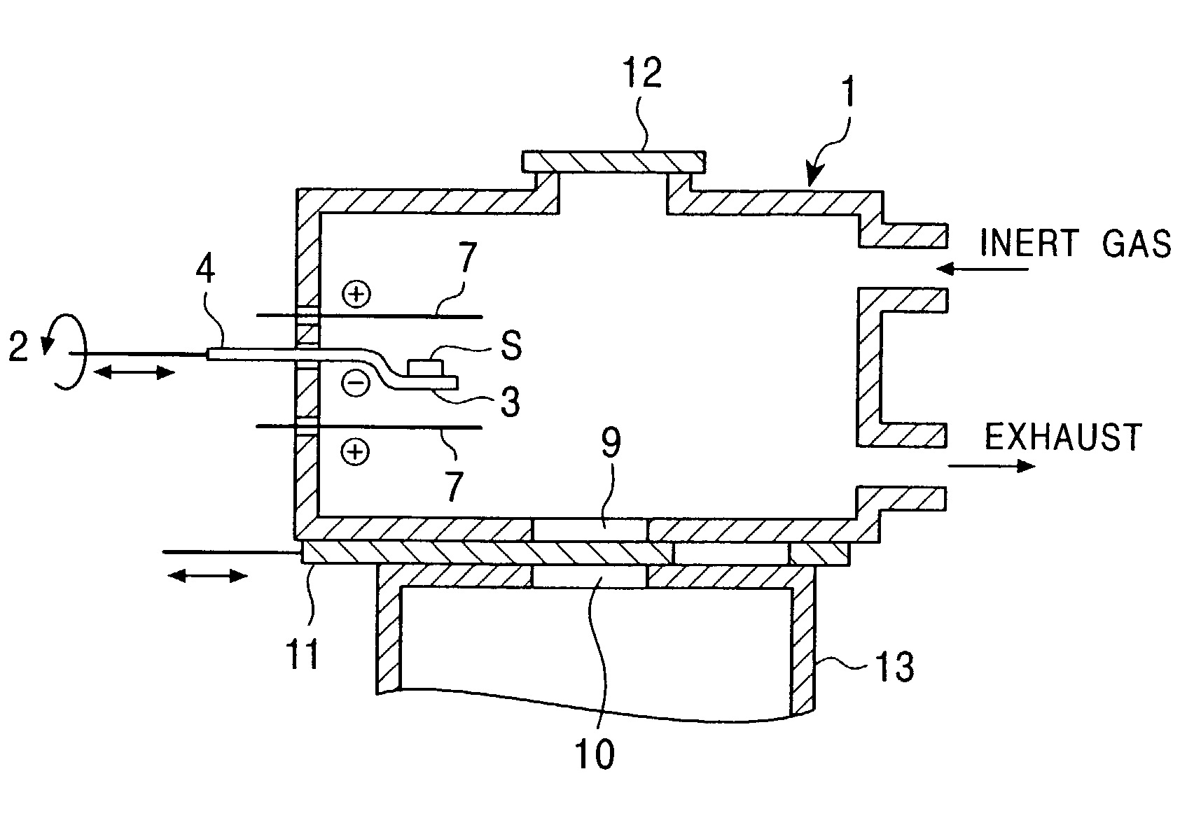
[0032] A steel sample of 6 mm .phi..times.5 mm was used as an analytical metal sample, and the oxygen content of the steel sample was determined by a melting-infrared absorption method in an inert gas. The results are shown in Table 1. In Table 1, the results of an example were obtained by oxygen analysis after pre-treatment by the pre-treatment apparatus of the present invention shown in FIG. 1. On the other hand, the results of a comparative example were obtained directly from oxygen analysis without pre-treatment. In the table, X represents the average value of oxygen contents measured 5 times for each of two samples A and B, and 6 represents the standard deviation (variation). These results indicate that in the example of the present invention, the analytical value of oxygen is about 1 to 2 ppm lower than that of the comparative example, and analysis accuracy is also improved. Also, as a result of surface analysis, the oxygen content corresponding to surface contaminants was est...


PUM

PropertyMeasurementUnit
pressureaaaaaaaaaa
surface areaaaaaaaaaaa
cylindrical shapeaaaaaaaaaa

Abstract

The present invention provides a pre-treatment apparatus for an analytical metal sample, the apparatus including (1) a treatment chamber having a sample charging port which can be opened and closed and provided at the top of the chamber, a sample discharging port which can be opened and closed and provided at the bottom of the chamber, and a gas inlet and gas outlet, (2) a sample carrying bar joined to a sample holder also used as a sputtering electrode, and provided to pass through at least one side wall of the treatment chamber so as to be substantially horizontally movable and axially rotatable, and (3) a sputtering counter electrode at least having portions arranged opposite to each other in a region not inhibiting the charge and discharge of an analytical metal sample so that the sample holder can be arranged in the counter electrode. The present invention also provides a pre-treatment method capable of simply cleaning the surface of the analytical metal sample by using the pre-treatment apparatus and preventing re-contamination of the cleaned sample by exposure to the air or the like. Furthermore, the present invention provides an analysis apparatus provided with the pre-treatment apparatus to permit high-accuracy quantitative determination of trace elements of metals.

Description

[0001] The present invention relates to a method and apparatus for pre-treating a metal sample (referred to as an "analytical metal sample" hereinafter) subjected to metal analysis. Particularly, the present invention relates to a pre-treatment method and pre-treatment apparatus for removing contaminants adhering to and / or adsorbed on the surface of a metal sample before analysis of trace elements in a metal. Also, the present invention relates to an apparatus comprising the pre-treatment apparatus, for analyzing elements in a metal.[0002] The trace elements of steel, for example, oxygen, carbon, nitrogen, and sulfur influence the material properties of steel, such as ductility, processability, etc., and accurate quantitative analysis is required. This is generally widely indicated in the fields of iron and steel industry and metal material industry with increases in purity of metal materials. Therefore, an apparatus and method for analyzing the elements in a metal with high accurac...

Claims


Application Information

Patent Timeline
Patent Type & Authority Applications(United States)
IPC IPC(8): G01N1/32G01N33/20
CPCG01N1/32G01N33/20G01N33/2022
Inventor ABIKO, KENJIYASUHARA, HISAONIIDA, TAKASHISHIMURA, MAKOTOIWAI, HIDEO
Owner JAPAN ANALYST CORP
Why Eureka
Try Eureka