
Magnetorheological dampers with improved wear resistance

a technology of magnetorheological dampers and dampers, applied in the manufacture of springs/dampers, shock absorbers, shock absorbers, etc., can solve the problems of affecting the wear resistance of dampers, the rate of material removal or wear rate is significantly more rapid, and the damage associated with high-stress abrasion is more severe. , to achieve the effect of improving the wear resistance of the damper body and improving the wear resistan

Inactive Publication Date: 2002-09-19
BWI CO LTD SA +1
View PDF0 Cites 74 Cited by
  • Summary
  • Abstract
  • Description
  • Claims
  • Application Information

AI Technical Summary

Benefits of technology

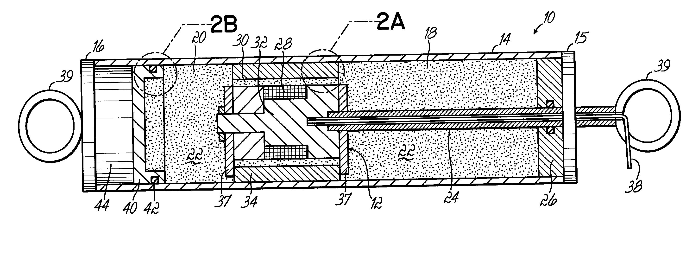
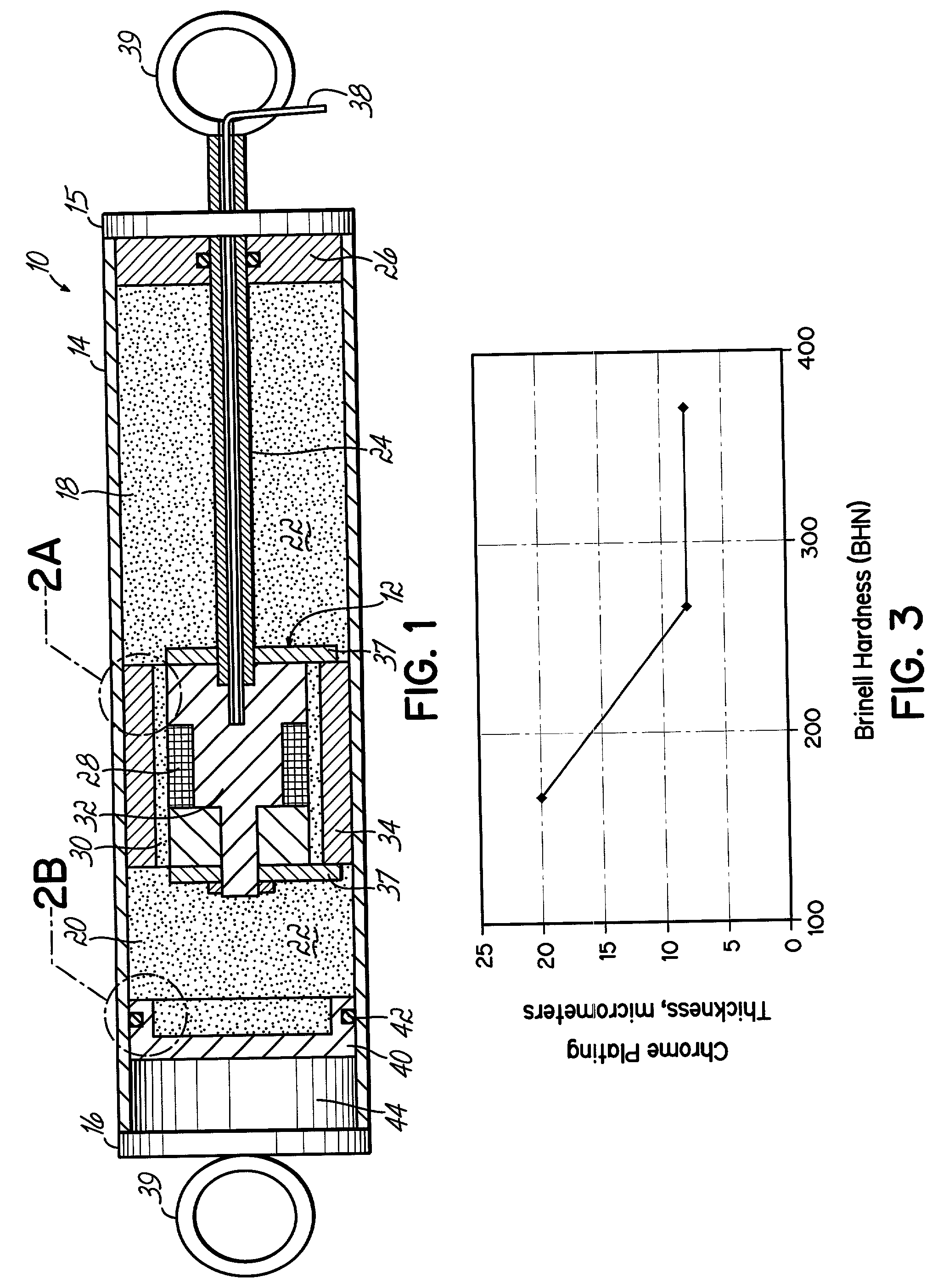
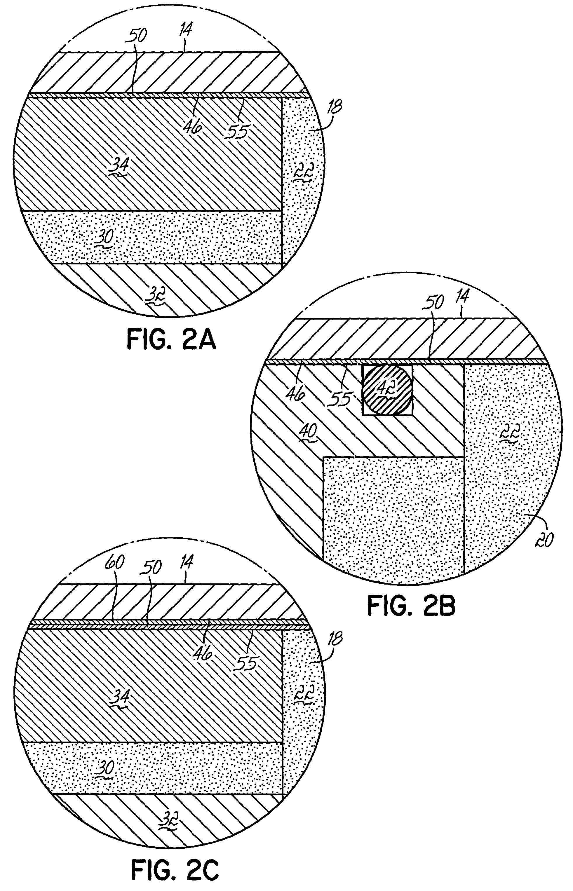
[0009] The present invention provides damper bodies for a magnetorheological (MR) damper and methods of improving the wear resistance of a damper body for an MR damper. Specifically, the wear resistance is improved by applying a thickness of hard chromium plating or chromium, greater than or equal to a minimum thickness, to the sliding wear surface of the damper body such that the wear mechanism is predominantly low-stress abrasive wear and the base material of the damper body does not experience significant high-stress abrasive wear over the vast majority of the service life of the magnetorheological damper.
[0011] In more specific embodiments, the magnetorheological damper further comprises a sealed interior space which is substantially filled with a magnetorheological fluid and divided into two chambers by the piston. The magnetorheological fluid comprises microparticles formed of a material exhibiting magnetorheological activity in the presence of a magnetic field and having a size distribution ranging between about 1 .mu.m and about 25 .mu.m. The piston includes a flow passageway that permits the magnetorheological fluid to flow between the two chambers. An electromagnetic is configured and positioned to selectively apply a magnetic field to the magnetorheological fluid flowing through the flow passageway for increasing the effective viscosity thereof.

Problems solved by technology

Plain carbon steel is known to experience "high-stress abrasion" during a stroke of the piston when microparticles penetrate through the sliding wear surface afforded by the hard chromium plating and are forced into the underlying plain carbon steel.
The surface damage associated with high-stress abrasion is more severe and the rate of material removal or wear rate is significantly more rapid than for a competing wear mode known as "low-stress abrasion."
Under conditions of high-stress abrasion, the sliding wear surface of the tubular body can rapidly deteriorate due to the presence of microparticles.
Once the sliding wear surface has been penetrated, high stress abrasion works to erode the underlying base material of the tubular body.
As the sliding wear surface and base material erodes, the hydraulic cylinder may experience a partial or complete loss of functional capability.
For example, the abrasive wear can increase the inner diameter of the tubular body near the portion of the sliding wear surface contacted by the piston.
In particular, the greatest loss in dampening force occurs for portions of the sliding wear surface near mid-stroke of the piston, where the piston has the most frequent residence during movement.
Accordingly, thin layers of hard chromium plating in the 5 .mu.m range do not offer significant resistance to penetration and the wear mode remains predominantly high-stress abrasion.
Microparticles become readily trapped between the piston and the sliding wear surface of the damper body.
High-stress abrasive wear rapidly erodes the sliding wear surface of the damper body and, as a result, conventional MR dampers are prone to premature and rapid failure at any of the various portions of the sliding wear surface.
Despite considerable efforts, manufacturers of conventional MR dampers have been unable to significantly prolong the service life of the damper body.
Although the application of a thin 5 .mu.m layer of a hard chromium coating would retard the failure rate of damper bodies, such thin layers would not prevent the occurrence of high-stress abrasive wear.
Thus, the service life of conventional MR dampers is significantly shortened by the deficient wear resistance of conventional damper bodies.

Method used


Image

  • Magnetorheological dampers with improved wear resistance
  • Magnetorheological dampers with improved wear resistance
  • Magnetorheological dampers with improved wear resistance

Examples


example

[0043] Testing was performed with a 1{fraction (13 / 16)} inch outer diameter, 1 / 2 inch long reciprocating piston made from nickel plated steel sliding on a 25 .mu.m thick chrome layer over 180 BHN steel. In accordance with the present invention, the threshold minimum thickness (t.sub.m) of the chrome layer on a 180 BNN steel is 17.9 .mu.m. Thus, the chrome layer is 7.1 .mu.m thicker than the minimum thickness required for low stress abrasive wear. Under a load of 120 N, the service life was greater than 6 million cycles with negligible wear of less than 3 .mu.m. Under a load of 240 N, the service life was greater than 4 million cycles with wear less than 8 .mu.m.

[0044] By comparison, testing was performed using the same reciprocating piston, but sliding on a 12 .mu.m thick chrome layer over 180 BHN steel. Thus, the chrome layer thickness is less than the determined threshold minimum thickness under a load of 120 N, the service life was less than 1 million cycles with the chrome layer...


PUM


Abstract

A damper body for a magnetorheological (MR) damper and associated methods of forming the damper body. The damper body is formed of a base material, such as a steel, and is coated with an abrasion-resistant layer comprising chromium. The layer of chromium provides a sliding wear surface for sliding contact with a reciprocating piston. To avoid high-stress abrasive wear over the expected service life of the magnetorheological damper, the layer of chromium has a minimum thickness greater than or equal to a minimum thickness of about 8 .mu.m. In other embodiments, be fore applying the abrasion-resistant layer of chromium, the damper body is coated with a layer of a hard coating material having a hardness greater than the hardness of the base material. The effective hardness of the damper body is a composite of the respective hardnesses of the base material comprising the damper body and the layer of hard coating material. The thickness of abrasion-resistant layer of chromium is chosen in direct relation to the effective hardness.

Description

FIELD OF THE INVENTION[0001] This invention relates to magnetorheological dampers and, in particular, to surface finishes for sliding wear surfaces of the damper body in magnetorheological dampers.BACKGROUND OF THE INVENTION[0002] Magnetorheological (MR) dampening devices or dampers are used in various automotive applications to dampen and control vibration, such as in suspension systems and engine mounts for vehicles, and in other applications for fluid-assisted actuation, such as flow-control valves, brake assemblies, and clutch assemblies. The MR damper device generally comprises a piston mounted within a damper body and adapted for sliding motion in sliding contact with the interior of the damper body. The damper body is typically formed of a plain carbon steel, which commonly has a hardness less than about 240 Brinell hardness number (BHN), and contains a volume of a magnetorheological (MR) fluid. The operation of the MR damper relies upon the unique properties of MR fluids, wh...

Claims


Application Information

Patent Timeline
Patent Type & Authority Applications(United States)
IPC IPC(8): F16F9/53
CPCF16F9/535F16F2226/02
Inventor LISENKER, IIYAHOPKINS, PATRICK NEILKRUCKEMEYER, WILLIAM CHARLES
Owner BWI CO LTD SA
Learn More