
Forced mist cleaning of combustion turbines

a combustion turbine and foam cleaning technology, applied in the direction of machines/engines, cleaning using liquids, lighting and heating apparatus, etc., to achieve the effect of minimizing the overall cleaning time, improving the effectiveness of most cleaning solutions, and maximum efficiency

Inactive Publication Date: 2002-09-19
GENERAL ELECTRIC CAPITAL AS AGENT
View PDF0 Cites 36 Cited by
  • Summary
  • Abstract
  • Description
  • Claims
  • Application Information

AI Technical Summary

Benefits of technology

[0024] The misted cleaning solutions described above provide acceptable cleaning results throughout a wide temperature range. While they typically function throughout the full temperature range where the underlying solution is liquid, i.e., from about 32.degree. F. to about 212.degree. F. for aqueous solutions, they are most often used at temperatures ranging from ambient, i.e., about 40-80.degree. F., to about 200.degree. F. Because the effectiveness of most cleaning solutions is improved at higher temperatures, most solutions are used at a temperature of about 150-180.degree. F. for maximum efficiency.
[0025] While the flow rate for these misted solutions can vary greatly, depending, on the initial pressure applied and the pressure drop through the turbine, the rate should be optimized to provide sufficient and complete contact while minimizing the overall cleaning time. The driving gas should be forced through the turbine at a flow rate of greater than about 0.2 linear feet per second, more preferably about 0.5 to 5.0 linear feet per second and most preferably about 1 to 2 linear feet per second. Those skilled in the art can readily calculate the linear flow rate based upon the internal volume of the turbine and the flow rate (cubic feet per minute) of the driving gas. These conditions should produce a residence time in the typical turbine (averaging 8-27 feet in length) of about no more than 40 to 135 seconds, preferably about 1.6 to 54 seconds and most preferably about 4 to 27 seconds.
[0026] While it is not necessary to turn the turbine during the cleaning operation, it is believed that contact with the misted cleaning solution is improved by slow cranking of the turbine. Accordingly, it is preferred that the turbine be turned at a speed not exceeding about 10 RPM, preferably about 5 RPM during the pumping operations.
[0029] When installed, the manifold of the present invention provides a convenient means for confining the misted cleaning solution and forcing it through the compressor section of a combustion turbine to perform the cleaning methods of the present invention. By employing the cleaning methods of the present invention, contaminants in both the compressor section and in the combustion and turbine sections of a combustion turbine are conveniently and effectively removed in order to improve the compressor and turbine discharge pressures and the turbine power output, thus improving the efficiency and economy of the combustion turbine.

Problems solved by technology

These contaminants often include heavy metals and their oxides, together with shellacs, varnishes and other hard combustion residues.

Method used


Image

  • Forced mist cleaning of combustion turbines
  • Forced mist cleaning of combustion turbines
  • Forced mist cleaning of combustion turbines

Examples


Embodiment Construction

[0038] The present invention provides improved methods for removing contaminants deposited on the blades and vanes of the compressor, combustion and turbine sections of a combustion turbine. The present invention provides improved, off-line methods for cleaning such turbines by using a manifold to pump a foamed cleaning solution through the air intake of the combustion turbine.

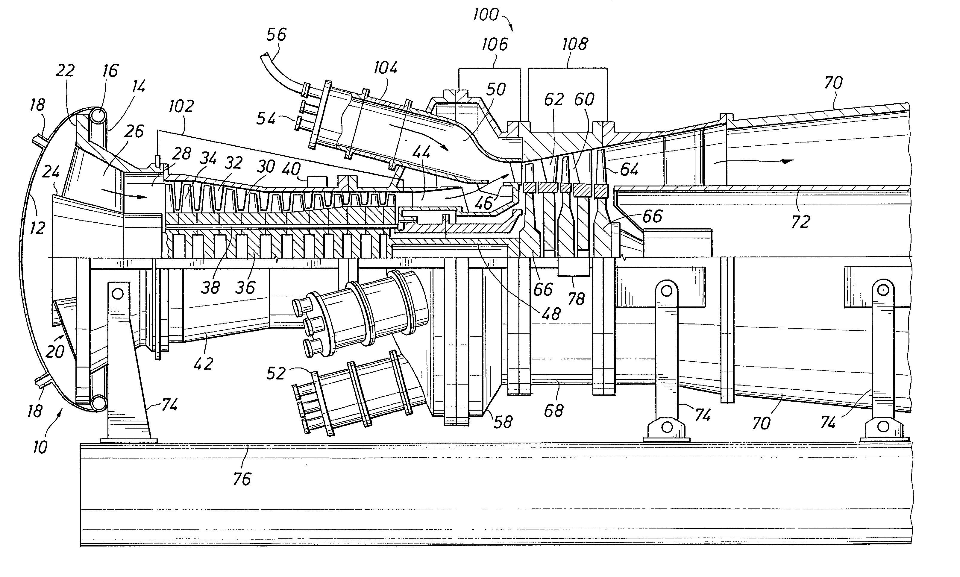
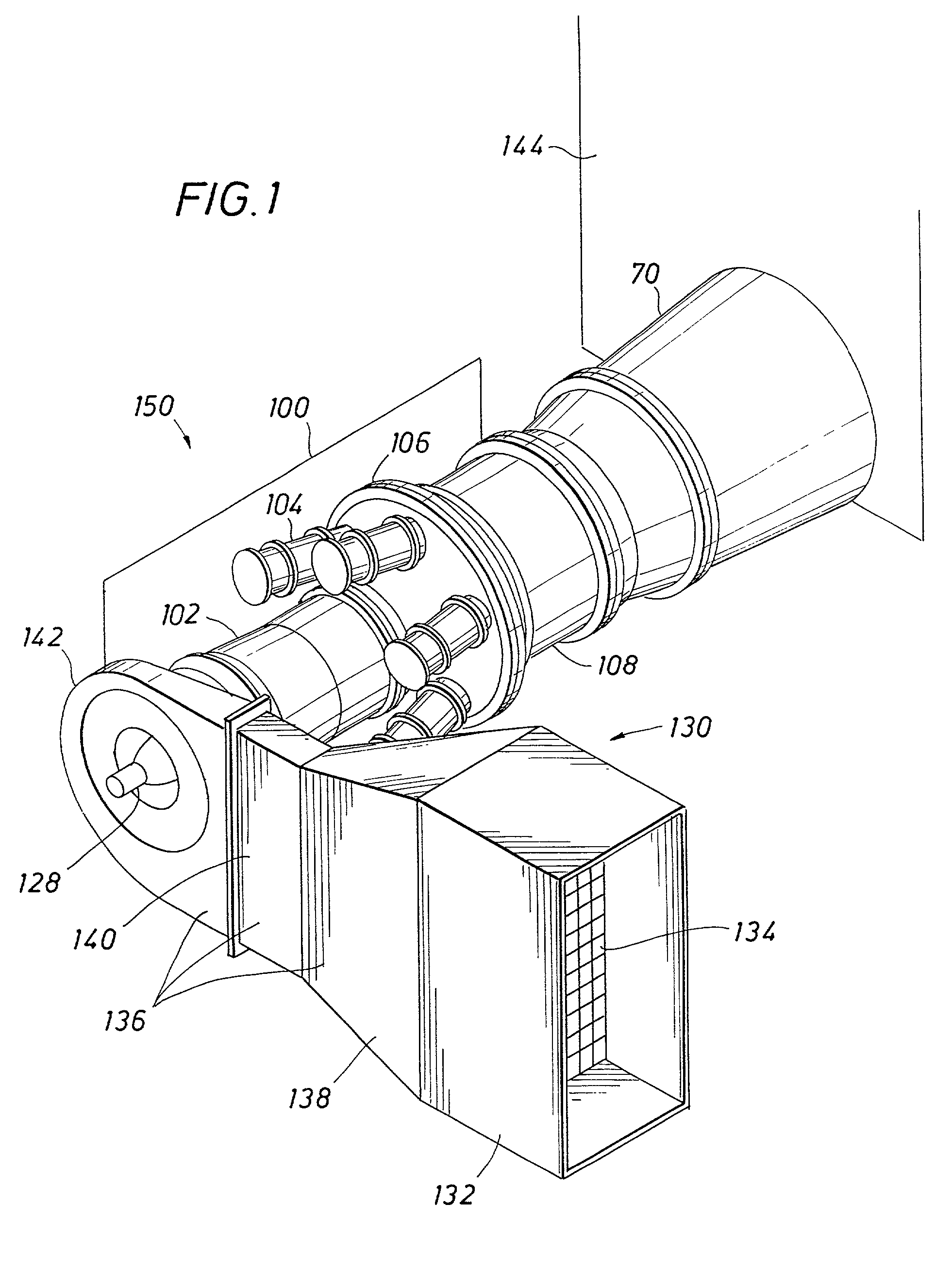
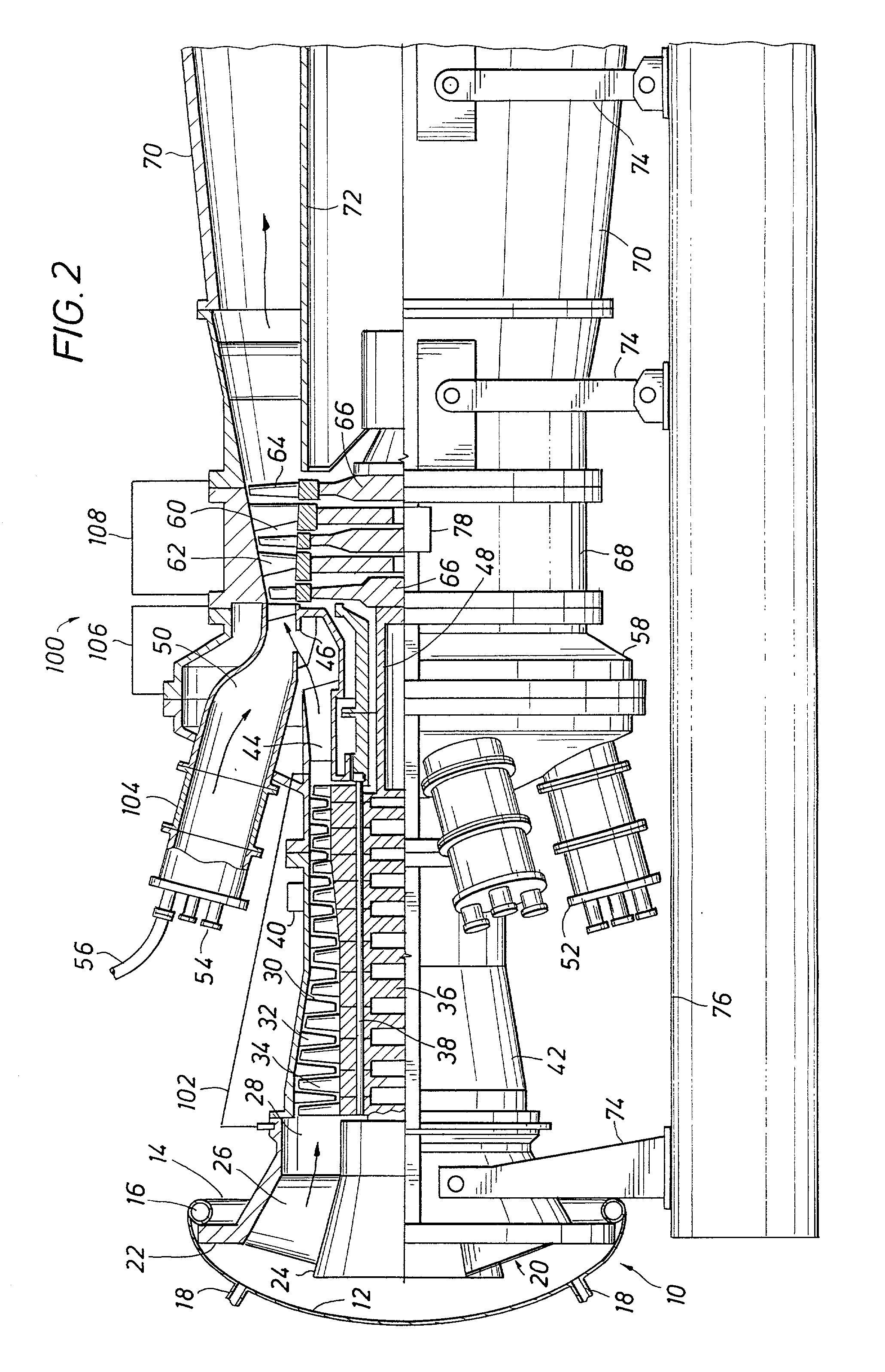
[0039] The present invention is readily understood by reference to the operation of an otherwise conventional, combustion turbine power generation facility such as illustrated in FIG. 1. FIG. 1 provides an overview of a combustion turbine power generation facility 150. Combustion turbine engine 100 is employed to generate electric power from the combustion of fuel with air. For simplicity, the associated electric generator is not illustrated in FIG. 1.

[0040] Depending on the installation, the electric generator can be driven from either the intake end of turbine engine 100 via shaft 128 or from the exhaust end...


PUM

PropertyMeasurementUnit
Angleaaaaaaaaaa
Angleaaaaaaaaaa
Temperatureaaaaaaaaaa

Abstract

The present invention is directed to methods for cleaning films and particulates from the compressor section and combustion contaminants from the combustion and turbine sections of a combustion turbine. Particulate films and contaminants adhering to the internal components of the compressor section of a turbine are readily removed by forcing a mist comprising a cleaning solution such as an aqueous surfactant solution through the compressor section. Contaminants resulting from fuel combustion and deposited in the combustion and turbine sections are removed by forcing a mist comprising a second cleaning solution through those sections. The second solution typically comprises an aqueous acid solution optionally including a corrosion inhibitor. The compressor section must be isolated from such acid solutions, e.g. by continuing to force the misted surfactant solution through the compressor section prior to and simultaneously with forcing the misted acid solution through the combustion section. A manifold suitable for providing a partial seal about the air intake of the compressor section and through which a misted cleaning solution can be pumped is also disclosed.

Description

BACKGROUND OF THE INVENTION[0001] I. Field of the Invention[0002] The present invention generally relates to methods for foam cleaning combustion turbines by forcing a mist comprising a cleaning solution through the turbine. More specifically, the present invention is directed to methods for cleaning contaminants adhering to the internal surfaces of the compressor, combustion and turbine sections of a combustion turbine by forcing one or more cleaning solution mists therethrough. Also discussed is a manifold for partially blocking the air intake opening of the compressor section of a combustion turbine to facilitate such cleaning.[0003] II. Description of the Background[0004] Combustion turbines are used in a multitude of applications, including aviation, shipping, chemical processing and power generation. In combustion turbine power generation facilities, efficiency can be improved by supplementing the electrical power generated directly from the combustion turbine with recovery un...

Claims


Application Information

Patent Timeline
IPC IPC(8): C23G1/00F01D25/00F02B77/04F02C7/00
CPCC23G1/00F01D25/002F02B77/04F02C7/00
Inventor RUIZ, R. DWANEFOSTER, CHARLES D.
Owner GENERAL ELECTRIC CAPITAL AS AGENT
Learn More