
Catalyst members having electric arc sprayed substrates and methods of making the same

a technology of catalyst members and substrates, applied in the field of catalyst members, can solve the problems of inability to spray materials, failure to achieve the effect of automotive catalyst substrates, and foams made of pure nickel or nickel-chromium alloys

Inactive Publication Date: 2002-09-12
ENGELHARD CORP
View PDF0 Cites 39 Cited by
  • Summary
  • Abstract
  • Description
  • Claims
  • Application Information

AI Technical Summary

Benefits of technology

0026] This invention can provide an improvement to a variety of devices that are powered by small engines and diesel engines that have exhaust treatment apparatuses, the improvement being that the ...

Problems solved by technology

Such combustion flame spray guns are said to operate at relatively low temperature and are often incapable of spraying materials having melting points exceeding 5,000.degree. F.
The Paper describes the use of various metal foams as catalyst substrates and notes that foams made of pure nickel or nickel-chromium alloys were not successful as substrates for automotive catalysts because of corrosion problems encountered in the environment of an automotive exhaust catalyst.

Method used


Image

  • Catalyst members having electric arc sprayed substrates and methods of making the same
  • Catalyst members having electric arc sprayed substrates and methods of making the same
  • Catalyst members having electric arc sprayed substrates and methods of making the same

Examples


example 1

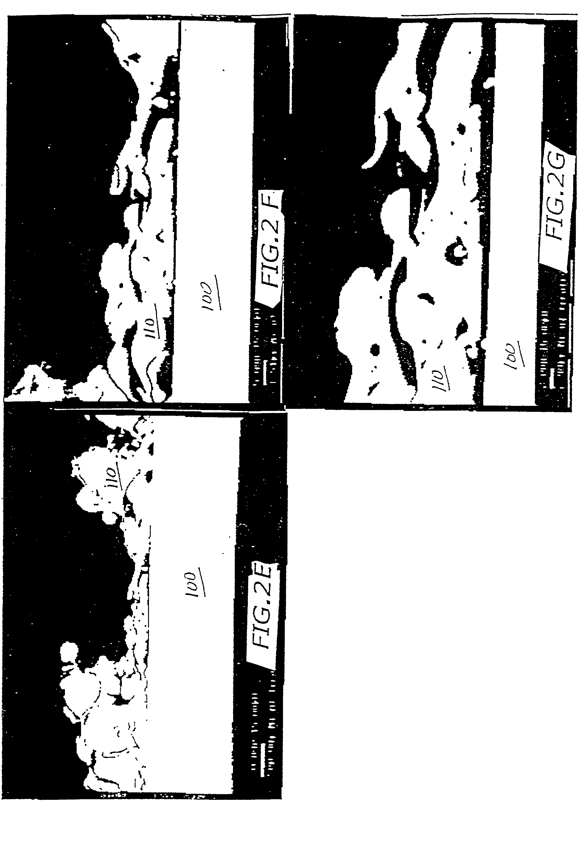
[0136] Six steel wire mesh substrates and a 100 cpsi metal honeycomb were each wire arc-sprayed using nickel aluminide wire as the anchor layer feedstock. The nickel aluminide wire had a diameter of {fraction (1 / 16)} inch (1.59 millimeters (mm)). The molten nickel aluminide alloy was sprayed at 11 lbs / hr with a gas pressure of 70 psi to deposit an anchor layer on the substrates at a stand-off of 6 inches. The spraying process on the 100 cpsi monolith successfully deposited an anchor coat in the interior gas-flow passages of the monolith.

[0137] One of the wire mesh substrates was subjected to temperature cycles in air at from about 100.degree. C. to 1000.degree. C. for 15 hours. After the temperature cycling, the mesh was examined and compared to a reference, and no difference between the surfaces of the two samples was noticed. A second wire mesh substrate was cycled for three hours from room temperature to about 930.degree. C. by heating in the flame of a Bunsen burner for about 6 ...

example 2

[0138] Three different catalyst members were prepared in tubular configurations suitable for use in the exhaust treatment apparatus of a small engine to function as tubular catalyst members in accordance with the present invention, as follows. First, a steel metal screen was wire arc spray-coated with a nickel-aluminide alloy as described in Example 1 to deposit an anchor layer on the substrate. The screen substrate was then coated with a catalytic material comprising around 1 to 3 weight percent platinum and rhodium, in a 5:1 weight ratio, as the principal catalytic species, at a loading of 0.31 grams per square inch of substrate (g / in.sup.2). The screen was then rolled into a tube having a diameter of about 1.75 inch and a length of about 7.25 inches, and it was tack-welded at three points along the seam to hold it together. This configuration had about 69 square inches of surface area on each side of the tube, for a total of 138 square inches.

[0139] Second, a metal herringbone fo...


PUM

PropertyMeasurementUnit
Fractionaaaaaaaaaa
Fractionaaaaaaaaaa
Fractionaaaaaaaaaa

Abstract

Electric arc spraying a metal onto a substrate produces an anchor layer on the substrate that serves as a surprisingly superior intermediate layer for a catalytic material deposited thereon. Spalling of catalytic material is resisted even when subjected to the harsh conditions imposed by small engines or in a close-coupled position for a larger engine.

Description

CROSS-REFERENCE TO RELATED APPLICATIONS[0001] This application is a continuation-in-part of co-pending U.S. patent application Ser. No. 09 / 071,663 in the name of Michael P. Galligan et al, filed May 1, 1998, and entitled "CATALYST MEMBERS HAVING ELECTRIC ARC SPRAYED SUBSTRATES AND METHOD OF MAKING THE SAME", which is incorporated herein by reference, and is a continuation-in-part of co-pending U.S. patent application Ser. No. 09 / 293,216 in the name of Michael P. Galligan et al, filed Apr. 16, 1999, and entitled "CATALYST MEMBERS HAVING ELECTRIC ARC SPRAYED SUBSTRATES AND METHODS OF MAKING THE SAME", which is incorporated herein by reference and which is a continuation-in-part of said U.S. patent application Ser. No. 09 / 071,663.BACKGROUND OF THE INVENTION[0002] 1. Field of the Invention[0003] The present invention relates to catalyzed substrates, that is, to catalyst members comprising a substrate on which is coated a catalytic material, and to methods of making such catalyzed substr...

Claims


Application Information

Patent Timeline
IPC IPC(8): B01D53/86F01N3/10B01D53/88B01D53/94B01J23/755B01J23/89B01J32/00B01J37/02B01J37/34C23C4/06F01N3/28
CPCB01D53/885B01D53/94B01J37/0225B01J37/0244B01J37/347F01N3/2853F01N3/2864F01N2450/02Y10T29/49345B01D47/00
Inventor GALLIGAN, MICHAEL P.BOND, ALBERT K.DETTLING, JOSEPH C.
Owner ENGELHARD CORP
Learn More