Eureka AIR delivers breakthrough ideas for toughest innovation challenges, trusted by R&D personnel around the world.

Mobile station receiver operable for both single and multi-carrier reception

Inactive Publication Date: 2002-09-12
NOKIA MOBILE PHONES LTD
View PDF16 Cites 53 Cited by
  • Summary
  • Abstract
  • Description
  • Claims
  • Application Information

AI Technical Summary

Benefits of technology

[0014] It is a first object and advantage of this invention to provide an improved multi-carrier receiver.[0015] It is a further object and advantage of this invention to provide an improved multi-carrier receiver for use in a mobile station that overcomes the foregoing and other problems, that is cost effective to implement, and that is synergistic with the use of a DCRX in a single carrier reception environment.

Problems solved by technology

However, and as will be shown below, none of these approaches provides an optimum solution.
However, the use of this approach would require a substantial increase in the required power consumption and circuit area, and sensitivity-penalties might be incurred as well.
Furthermore, the required frequency synthesizers for the multiple DCRXs would be required to operate very close to one another in the frequency plane, resulting in possible interference effects occurring.
While the use of an image rejection mixer should provide some assistance in rejecting interfering channels, this approach is impractical from at least a cost-effective implementation perspective.
However, it can be shown that IQ-imbalances on the analog side of the receiver restrict the image rejection to about 30 dB, when about twice as much image rejection may be needed.
However, in this approach the dynamic requirements of the ADC become too stringent to provide a cost-effective implementation.

Method used


Image

  • Mobile station receiver operable for both single and multi-carrier reception
  • Mobile station receiver operable for both single and multi-carrier reception
  • Mobile station receiver operable for both single and multi-carrier reception

Examples


Embodiment Construction

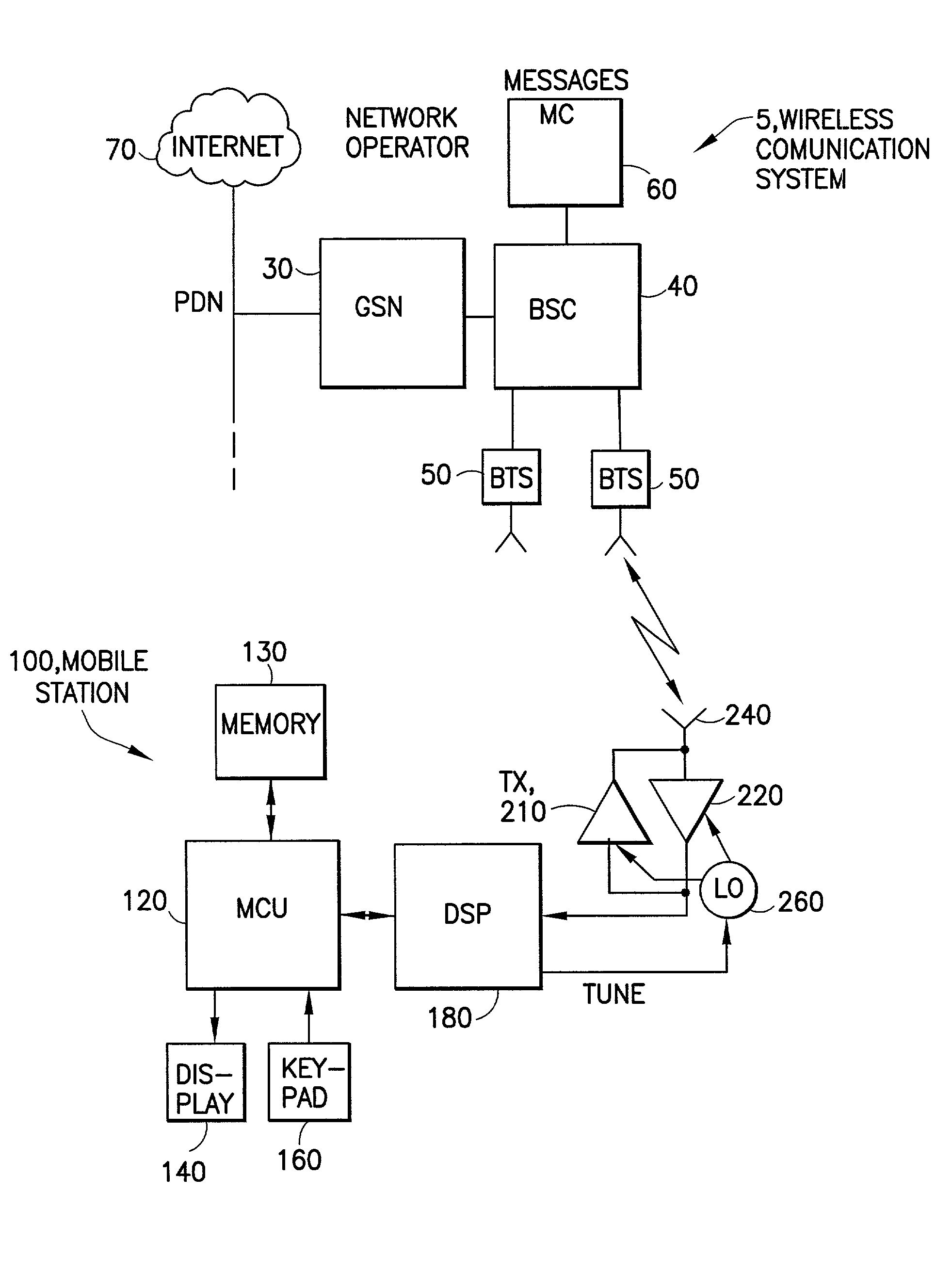
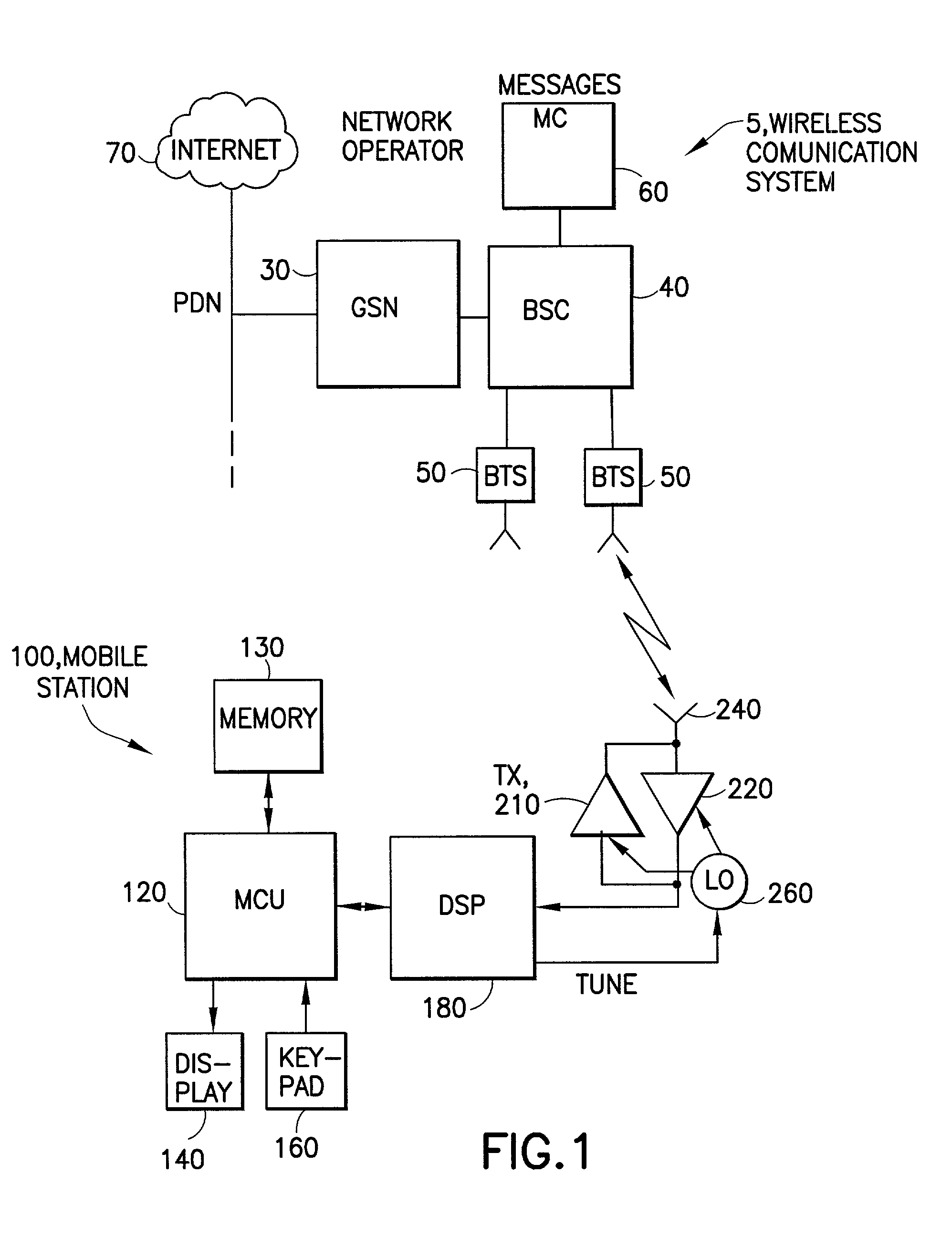
[0034] Referring first to FIG. 1, there is illustrated a simplified block diagram of an embodiment of a wireless communications system 5 that is suitable for practicing this invention. The wireless communications system 5 includes at least one mobile station (MS) 100. FIG. 1 also shows an exemplary network operator having, for example, a GPRS Support Node (GSN) 30 for connecting to a telecommunications network, such as a Public Packet Data Network or PDN, at least one base station controller (BSC) 40, and a plurality of base transceiver stations (BTS) 50 that transmit in a forward or downlink direction both physical and logical channels to the mobile station 100 in accordance with a predetermined air interface standard. A reverse or uplink communication path also exists from the mobile station 100 to the network operator, which conveys mobile originated access requests and traffic. It is assumed for the purposes of this invention that the BTS 50 has multi-carrier transmission capabi...


PUM


Abstract

In accordance with a method for single-carrier and multi-carrier reception, the following steps are executed: downconverting a received RF signal to in-phase (I) and quadrature (Q) channel signals each containing a plurality of sub-carriers at a low intermediate frequency (low-IF) and, if required, one sub-carrier or a single carrier centered around 0 Hz; filtering interfering signals outside of a frequency band of interest with analog lowpass filters in the I and Q channels; converting the I and Q channel signals to digital representations thereof; in the multi-carrier reception case, separating sub-carriers that are images of one another by quadrature downmixing the digital representations of the I and Q channel signals to baseband in the digital domain; and digitally adding or subtracting resulting I and Q signals to obtain one or both of an upper sideband and a lower sideband containing desired ones of the multi-carriers. For a symmetric multi-carrier reception case the step of downconverting includes a step of tuning a local oscillator to a center frequency of a group of sub-carriers, while for an asymmetric multi-carrier reception case the step of downconverting includes a step of tuning a local oscillator between a middlemost sub-carrier and its interfering adjacent channel.

Description

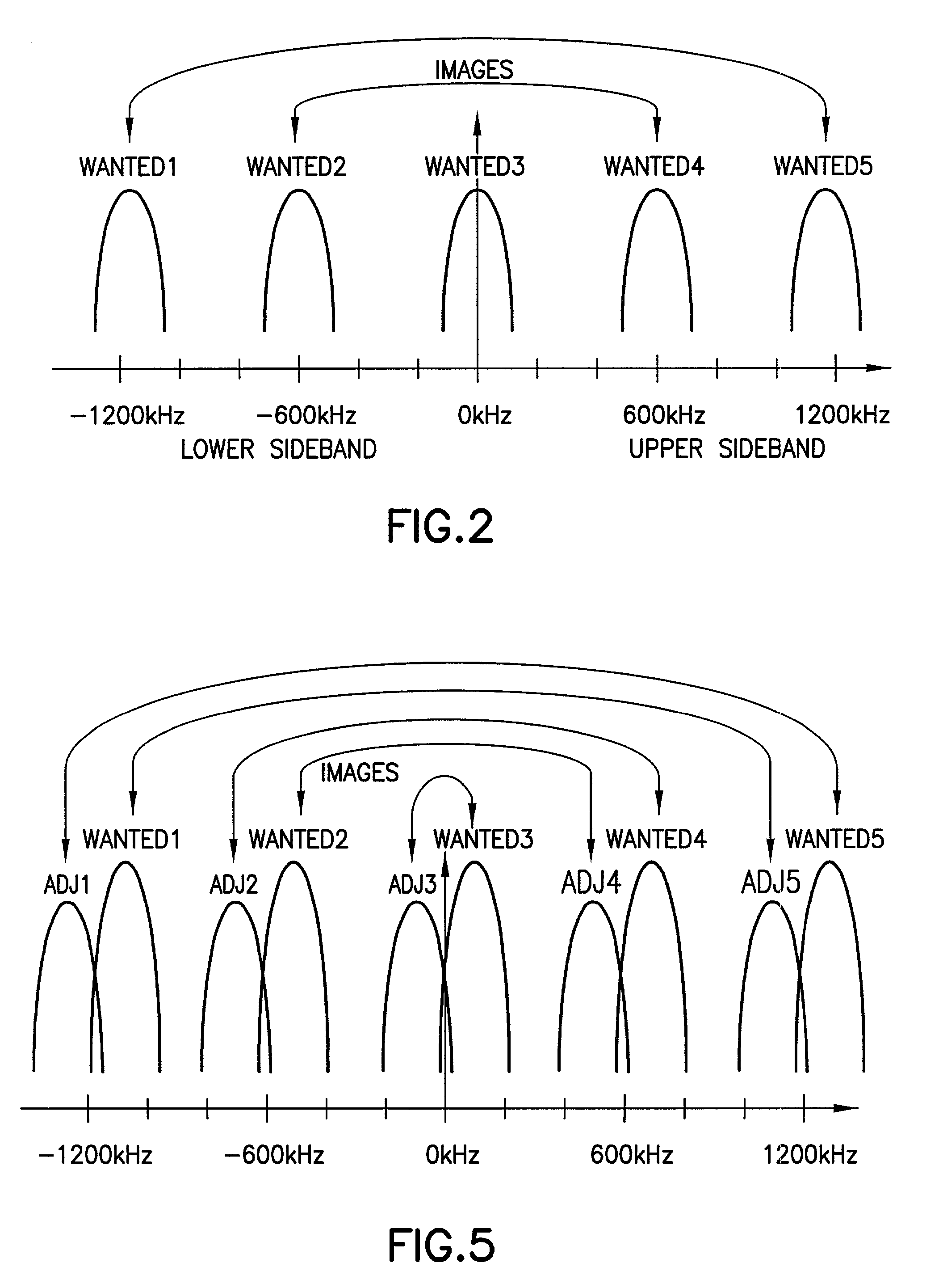
FIELD OF THE INVENTION[0001] This invention relates generally to wireless communications systems and methods and, more specifically, relates to RF receivers capable of receiving multiple carrier frequencies (multi-carriers).BACKGROUND OF THE INVENTION[0002] Modern wireless telecommunications systems are evolving to provide high speed packet data services for users of mobile equipment. One example is an ability to provide internet access to a user of mobile equipment. One wireless system that is rapidly evolving in this direction is a Time Division, Multiple Access (TDMA) system known as the Global System for Mobile Communication (GSM), in particular enhanced versions of GSM known as GSM+, GPRS (General Packet Radio Services) and EGPRS (Enhanced General Packet Radio Services).[0003] As such modern wireless communication system evolve it is inevitable that user demand will increase for higher speed data connections. One particularly attractive technique for increasing the effective da...

Claims


Application Information

Patent Timeline
IPC IPC(8): H03D3/00H04L27/227H03D7/16H04J1/00H04L5/06
CPCH03D3/009H03D7/166H04L5/06
Inventor HAAPOJA, SAMIHAMALAINEN, MIIKKA
Owner NOKIA MOBILE PHONES LTD
Why Eureka
Eureka Blog
Learn More