Hydraulic system for pivoting the lateral structural parts of a truck upwards and downwards

Inactive Publication Date: 2007-06-14
WEBER GISELA
View PDF4 Cites 4 Cited by
  • Summary
  • Abstract
  • Description
  • Claims
  • Application Information

AI Technical Summary

Benefits of technology

[0007] The object of the invention is to create a hydraulic system that c

Problems solved by technology

However, significant safety issues can occur with this arrangement.
In addition, an uneven pressure increase will occur in the hydraulic lines, as the respective piston rod is directed through one of the two oil chambers of each dual-action hydraulic cylinder, and thus the relevant oil chamber pressurizes the piston over a smaller cross-sect

Method used


Image

  • Hydraulic system for pivoting the lateral structural parts of a truck upwards and downwards
  • Hydraulic system for pivoting the lateral structural parts of a truck upwards and downwards
  • Hydraulic system for pivoting the lateral structural parts of a truck upwards and downwards

Examples


Embodiment Construction

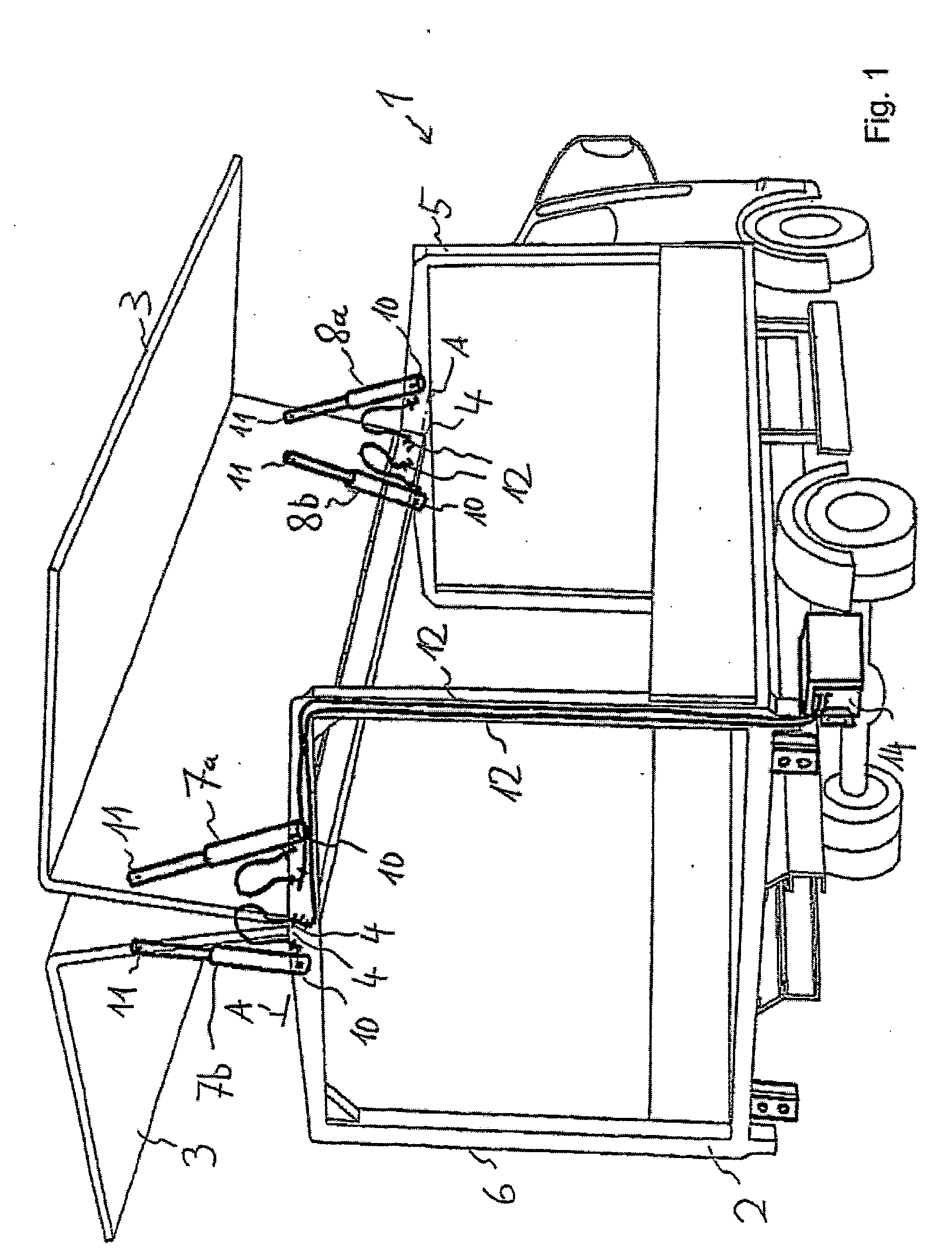
[0026] A truck 1 has a superstructure 2 and two wing components 3, which are mounted on the superstructure 2 in two parallel pivot axes A that extend in the longitudinal direction of the vehicle. The wing components 3 or wing bodies are constructed such that their cross-sections form right angles, so that when pivoted down they enclose the cargo area of the truck 1 on three sides, and in the upward pivoted or extended position shown in FIG. 1 they allow lateral access to the cargo area. The two pivot axes A of the two wing components 3 are accordingly positioned relatively close to one another at the center area of the truck 1, with bearings 4 in a front frame section 5 and a rear frame section 6 of the superstructure 2.

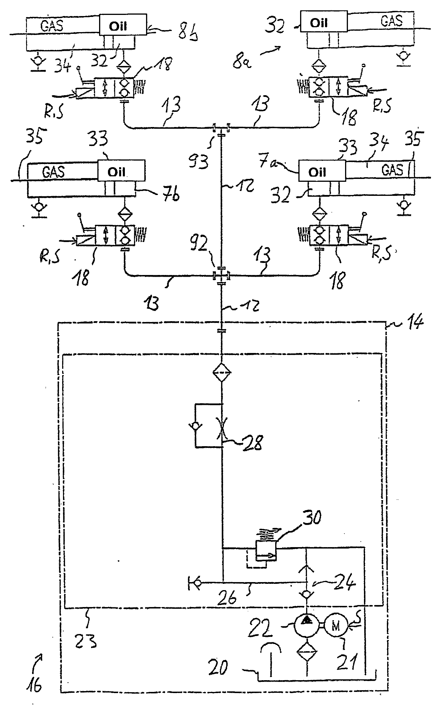
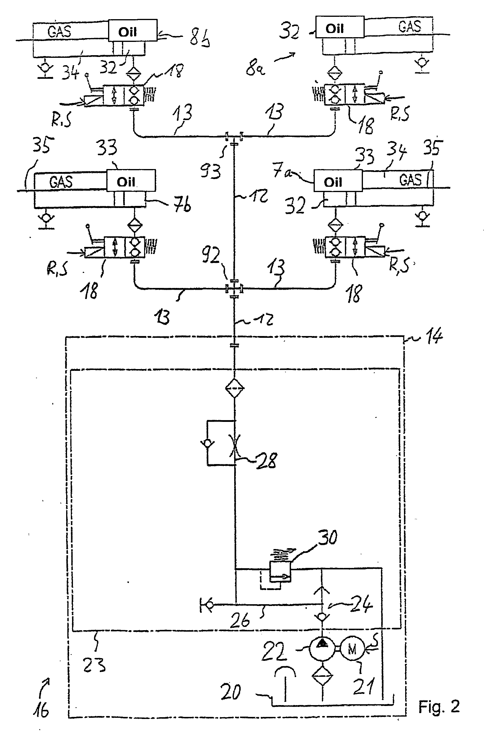
[0027] The wing components 3 are each pivoted via a rear hydraulic cylinder 7a or 7b, respectively, and a front hydraulic cylinder 8a and 8b, respectively, which are hinged at bearing points 10 on the superstructure and at bearing points 11 on the wings. The hydraul...


PUM


Abstract

Hydraulic system for pivoting the lateral structural parts of a truck upwards and downwards. Hydraulic system includes a hydraulic control unit provided with a hydraulic pump and hydraulic valves; a first hydraulic cylinder and a second hydraulic cylinder for pivoting a first component; and a third hydraulic cylinder and a fourth hydraulic cylinder for pivoting a second component. The hydraulic cylinders are embodied in a single-acting manner with an oil chamber and a spring counteraction. A check valve is provided between the at least one external hydraulic line and the oil chambers, the check valve blocking or enabling a reflux of the hydraulic liquid from the oil chamber into an external hydraulic line. In regulated positions of the lateral structural parts and when the hydraulic pump is not actuated, the check valve blocks backflow of the hydraulic liquid from the oil chamber and the external hydraulic line is depressurized.

Description

CROSS-REFERENCE TO RELATED APPLICATIONS [0001] This application is a continuation of application no. PCT / EP2005 / 005425, filed May 19, 2005, which claims the priority of German application no. 10 2004 031 202.8, filed 28 Jun. 2004, and each of which is incorporated herein by reference. [0002] The invention relates to a hydraulic system for pivoting wing components of a truck upward and downward. FIELD OF THE INVENTION [0003] Wing components of this type on a truck, also called wing bodies, are pivotably attached to the upper side of the truck superstructure and can be pivoted upward to allow lateral access to the truck's cargo area. BACKGROUND OF THE INVENTION [0004] Wing bodies or wing components of a truck are customarily pivoted upward and downward by means of dual-action hydraulic pistons. To accomplish this, a control unit is provided, for example on the truck's underbody, with a hydraulic pump that is actuated via a motor and itself controls eight external hydraulic lines, name...

Claims


Application Information

Patent Timeline
IPC IPC(8): F16D31/02B60J5/04B60J7/057E05F15/04F15B13/06F15B15/20
CPCF15B13/06F15B15/202
Inventor WEBER, GISELA
Owner WEBER GISELA
Why Eureka
Try Eureka