
Support and alignment device for enabling chemical mechanical polishing rinse and film measurements

a technology of support and alignment device, which is applied in the direction of manufacturing tools, grinding machine components, edge grinding machines, etc., can solve the problems of time-consuming and introduce errors in the processing of wafers

Inactive Publication Date: 2002-08-08
GLOBALFOUNDRIES US INC
View PDF0 Cites 12 Cited by
  • Summary
  • Abstract
  • Description
  • Claims
  • Application Information

AI Technical Summary

Benefits of technology

[0009] It is therefore another object of the invention to provide a support and alignment device that saves significant process time and improves CMP process control loop effectiveness.

Problems solved by technology

This is time consuming and introduces error into the processing of wafers.

Method used


Image

  • Support and alignment device for enabling chemical mechanical polishing rinse and film measurements
  • Support and alignment device for enabling chemical mechanical polishing rinse and film measurements
  • Support and alignment device for enabling chemical mechanical polishing rinse and film measurements

Examples


first embodiment

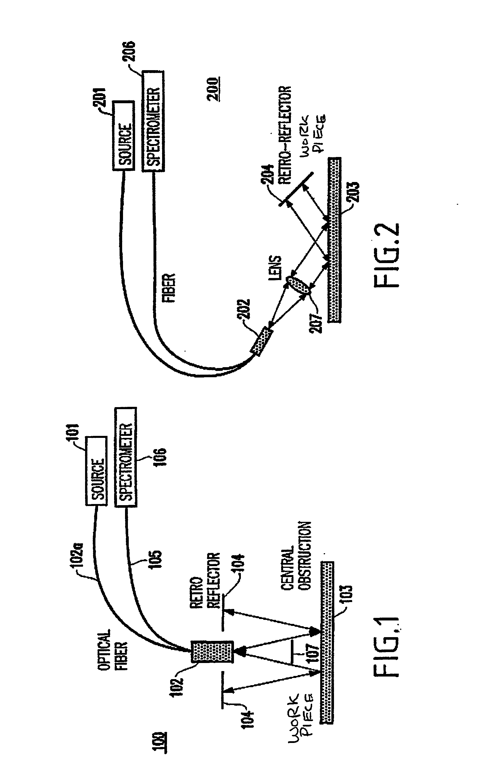
[0030] FIG. 1 illustrates the probe head design, and more specifically to a near normal incidence probe 100 that has been used in early process layers of semiconductor parts.

[0031] In FIG. 1, light is emitted from a source 101 along a fiber 102a in a cone, reflects off the wafer surface 103 under test, and retro reflects off a retro-reflector 104. The light returns to the fiber bundle 102 along the path it came through the wafer 103. A central obstruction mask 107 is placed to prevent specular (single pass) light from returning to the bundle. The light is measured by a detector 106 (e.g., a spectrometer).

[0032] Light that scatters from surface topography is effectively lost from the beam and does not return to the detector fiber 105 and that the light travels through the film stack twice. This effectively makes the probe most sensitive to the planar regions of the wafer 103 where light is specularly reflected. In this case, the range of angles is constrained by the numerical apertur...

second embodiment

[0033] FIG. 2 illustrates a collimated beam at a large angle of incidence in a probe 200 according to the probe, having a source 201, fiber bundle 202, retroreflector 204, fiber 205, and detector 206 similar to those of FIG. 1. An objective lens 207 is provided between the fiber bundle and 202 and the wafer 203 for focusing the output from the wafer.

[0034] The probe 200 inherits the property that topography is rejected and improves overall interference signal contrast by constraining the range of angles. This range of angles may be tailored to the application. Small spot or narrow beam profiles can be achieved with this configuration. Both FIGS. 1 and 2 are effectively confocal in that they take light from a small aperture and return it through a small aperture. This also contributes to good interference signal contrast. In both cases, the detector 106, 206 is a spectrometer connected to the probe by a bundle of one or more fibers.

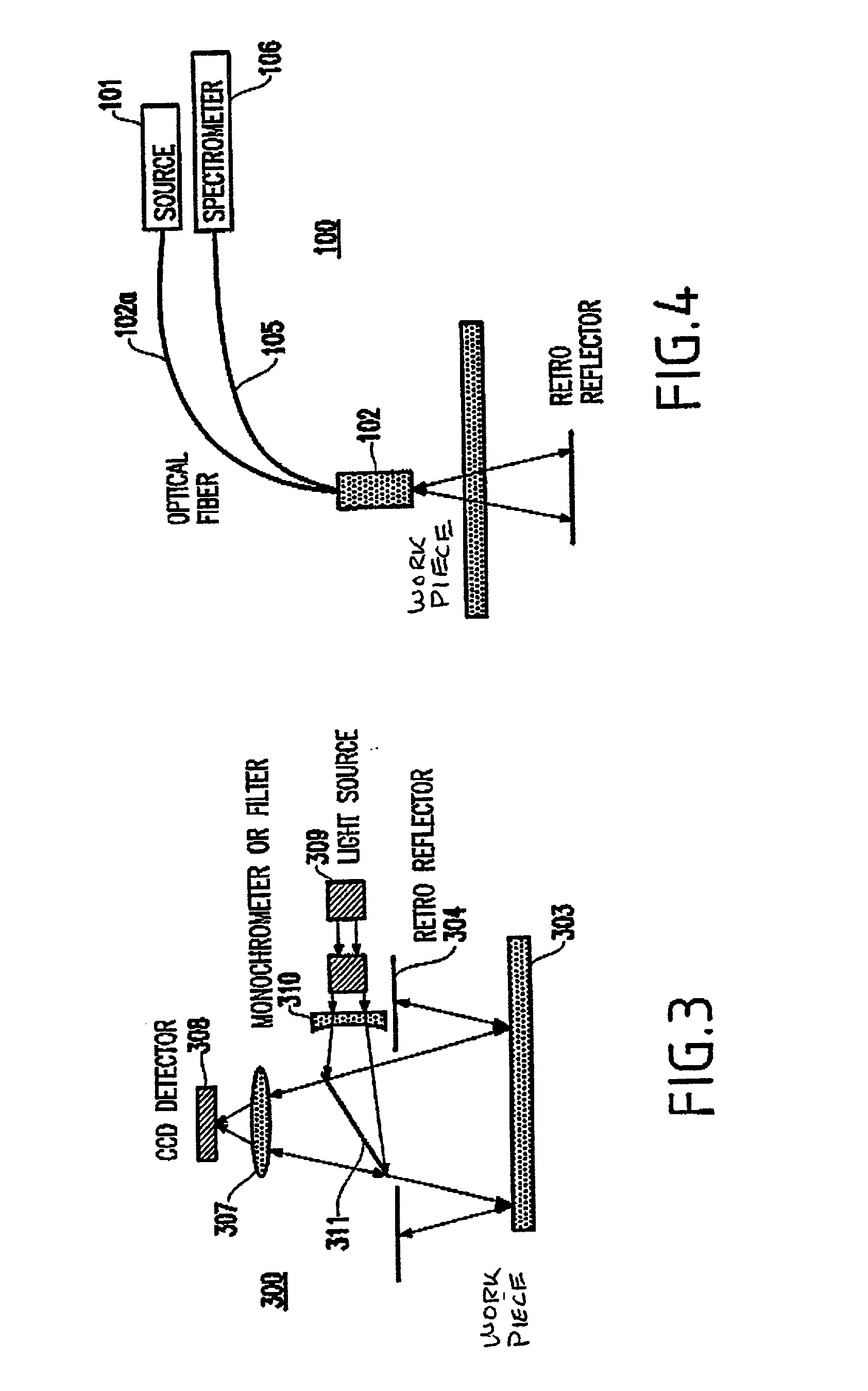
[0035] FIG. 3 illustrates the use of the multipass c...


PUM


Abstract

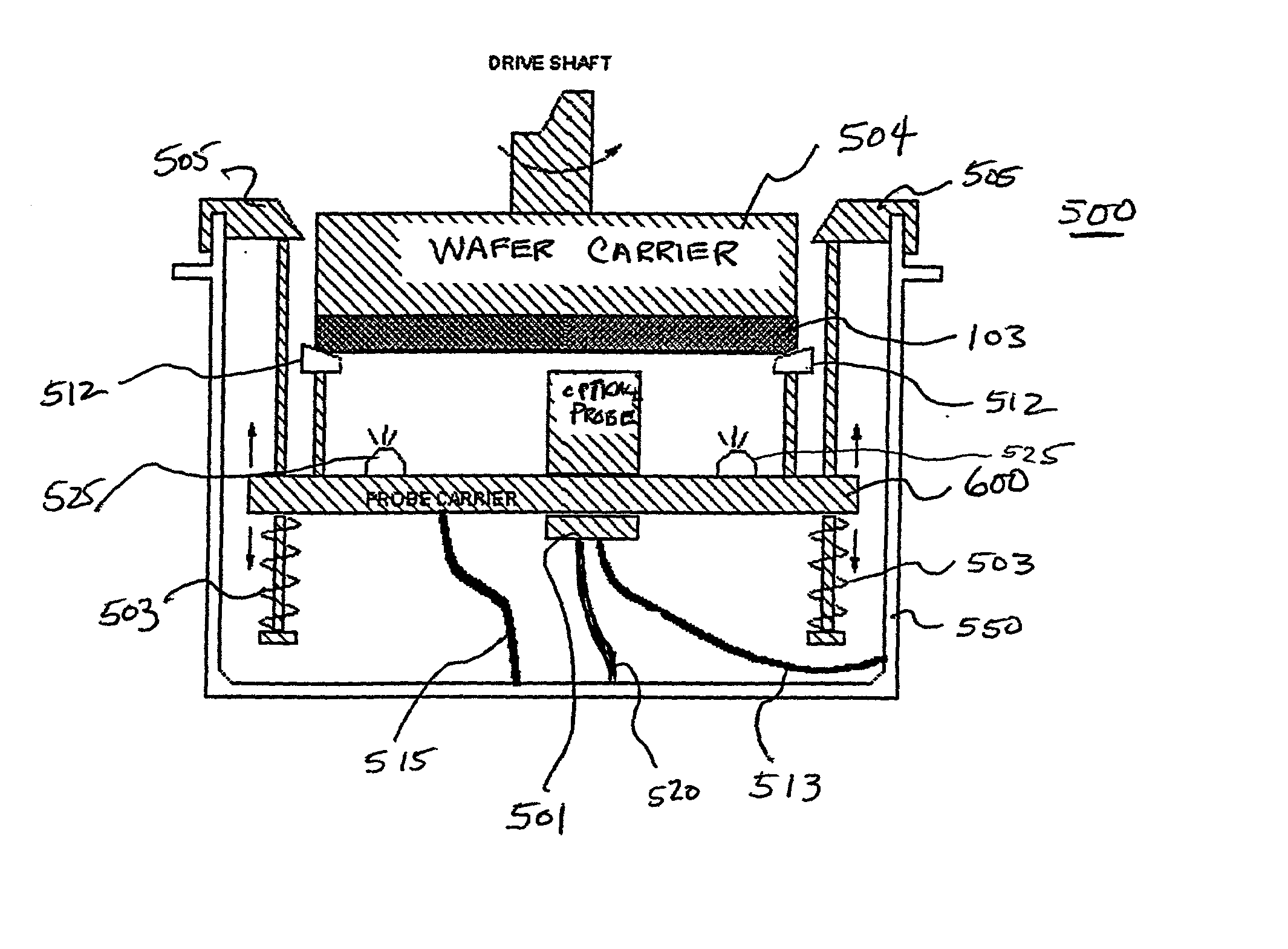
A device and method for providing precision alignment and support for an optical film measurement probe in the wafer rinse tank of a CMP polish tool. The device includes of a probe carrier, and spring loaded support guides attached to a support ring that supports and locates the mechanism in the rinse tank of the CMP tool. The probe carrier has multiple beveled bearing pads (three or more) that contact the rim of the rotating wafer chuck. Pressure from the chuck against these pads forces the probe carrier to maintain a fixed distance and orientation relative to the wafer while allowing the smooth rotation and motion of the wafer and chuck. Further, an integrated the wafer spray nozzles can be attached to the probe carrier that is located so as to minimize interference between wafer spraying and the probe carrier.

Description

[0001] 1. Field of the Invention[0002] This invention relates generally to chemical mechanical planarization or polishing (CMP) tools and, more particularly, to a device for supporting and maintaining proper alignment of a probe for measuring film thickness during a chemical-mechanical rinse phase of wafer processing.[0003] 2. Description of the Related Art[0004] Briefly, the chemical mechanical polishing process requires that a workpiece be held, with the desired coated surface face down, on a polishing pad supported on a rotating table, in the presence of an abrasive slurry. A chemical mechanical polishing machine can include a single rotating polishing plate and a smaller diameter rotating wafer carrier to which a wafer (or wafers) is (are) mounted. The wafer carrier is held above the polishing plate, in either a stationary fixed position or oscillating back and forth in a predetermined path, while both polishing plate and wafer carrier are rotated about their respective center a...

Claims


Application Information

Patent Timeline
Patent Type & Authority Applications(United States)
IPC IPC(8): H01L21/68
CPCH01L21/681
Inventor LEBEL, RICHARD J.MAURER, FREDERICNADEAU, ROCKSMITH, PAUL H. JR.WICKRAMASINGHE, HEMANTHA K.KESSEL, THEODORE G. VAN
Owner GLOBALFOUNDRIES US INC
Learn More