
Drug profiling apparatus and method

a profiling apparatus and drug technology, applied in the field of drug profiling apparatus and method, can solve the problems of large information loss in the averaging process, limited analysis of art spectral analysis techniques, and limited analysis of single channel or comparison of two channels, so as to improve the discrimination of physiological similarities, improve the accuracy of drug evaluation, and reduce the cost of toxicology testing.

Inactive Publication Date: 2002-05-16
BRIGHT IDEAS
View PDF0 Cites 33 Cited by
  • Summary
  • Abstract
  • Description
  • Claims
  • Application Information

AI Technical Summary

Benefits of technology

[0015] It is also an object of the present invention to provide a method for improved drug modeling for evaluating the benefits of drugs and side-effect predication in relation to an observed entity (e.g., human or animal).
[0136] A similarity matrix 78 also provides the ability to perform improved, more objective drug modeling. Similar to the engineer who places his model plane in a wind tunnel to see how a complete plane will act in actual flight, a drug researcher may apply a particular drug in an animal test and accurately predict how it will affect humans. For example, suppose the effects of drug X on humans as well as rats are well known and documented. In an ERI 10 comparison it is found that a newly discovered drug Y produces a signature or "fingerprint" in a rat very similar to that of drug X. A prediction using an ERI 10 in accordance with the present invention may provide much more accurate predictions or extrapolations to humans because the similarity is not calculated from symptoms. Rather, the similarity may be objectively measured in the fundamental effects the drug has on a particular and fundamental aspect of the observed entity, such as the brain.

Problems solved by technology

One of the disadvantages of prior art spectral analysis techniques is that they are generally limited to the analysis of a single channel or the comparison of two channels at a time.
While useful for certain applications, averaging techniques have several significant drawbacks.
For example, large quantities of information may be lost in the averaging process as only those signals that are robustly time-locked to a stimulus or response are able to survive the summation over multiple-trials.
Another serious disadvantage is that the averaging process only provides a comparison between groups of trials rather than between individual trials themselves.
Additionally, the need to first record multiple trials before a reliable evoked potential (EP) can be obtained tends to reduce the utility of signal averaging for real-time applications.
Therefore, there is no spatial information and, accordingly, inter-channel relationships are often missed.
Moreover, these prior art alternate approaches have not been integrated with computerized condition discrimination.
Like spectral analysis techniques, these alternate prior art approaches rely on human visual inspection of the generated waveforms in concluding findings, which produces a review process fraught with the potential of observer error.
These prior art filtering methods tend to ignore frequency, and often temporal information as well.
Additionally, these prior art spatial analysis techniques must be applied to averaged evoked potentials or the noise level is prohibitive.
The foregoing prior art spatial filtering methods therefore are not typically useful for single-trial analysis.
The traditional neural network approaches, however, generally take a long time to program and learn, are difficult to train and tend to focus on local minima to the detriment of other more important areas.
Moreover, most of these analysis techniques are limited by a lack of integration with time, frequency and spatial analysis techniques.
To this end, the prior art methodologies for evaluating waveforms have significant weaknesses and limitations, and none seem to meet the goals of rapid accurate analysis of all pertinent characteristics of a wide variety of single-trial waveforms.

Method used


Image

  • Drug profiling apparatus and method
  • Drug profiling apparatus and method
  • Drug profiling apparatus and method

Examples


example ii

[0169] Referring now to FIG. 35, the brain activation value plot comes from data collected during a one hour EEG study on a freely behaving rat. Fast acting Brevital (3 mg / kg, 150 uL) was administered intravenously at 10, 15, 20, 25 and 30 minutes. Pentobarbital (10 mg / kg, 0.1 mL) was given intravenously at 35 minutes. A single EEG electrode in the rat brain was sampled at 10 KHz. Each data point in the above brain activation value plot represents one second of highly processed EEG. The method of processing the EEG was derived from a pattern learning algorithm that trained on EEG data taking just before and just after the Brevital injection at 30 minutes. The EEG training data was taken from 100 seconds recorded from 28:10 until 29:50 and 180 seconds recorded from 30:10 until 33:10. Each data point represents the degree of presence of a learned combination of phase-encoded frequencies between 1,000 and 3,000 Hertz.

[0170] As shown in the above brain activation value plot, fast acting...

example iii

[0171] Referring now to FIG. 36, a "cognitive comprehension" study was conducted on a human subject who viewed a computer screen displaying a written sentence describing a situation in a picture scene such as "The horse is kicking the man." The subject first read the sentence and viewed a correct picture (such as the picture of the horse kicking the man) and also some incorrect pictures (such as the picture of the man sitting on the horse). The pictures were then presented sequentially (one at a time) on the screen while five channels of raw EEG data were recorded from the subject's scalp.

[0172] Nine 1,100 ms epochs (columns) of raw EEG signal data are shown in FIG. 36. Note that it is difficult to visually discern discriminant patterns in the five raw EEG signal channels.

[0173] The cognitive EEG signal channel is a highly processed combination of EEG data from the five raw EEG signal channels and five epochs. A particular weighting pattern has been learned (discovered) and applied ...

example iv

[0176] Referring now to FIG. 37, notice that the three raw EEG signals (254, 255 and 256) do not reveal the presence or location of a light flash. Rather, the tiny light flash signal is obscured in background brain activity noise. This noise stems from other neuronal processing unrelated to the signal of interest. The signal of interest is exclusively correlated with the presence and location (right or left) of a brief visual flash stimulus.

[0177] Notice that the enhanced EEG signal 1 readily reveals the presence or absence of a visual checkerboard flash stimulus in the lower left quadrant of the subject's visual field. The subject's eyes were fixated on a point in the center of a computer monitor while 30 millisecond checkerboard flashes were presented at random times and locations in the four quadrants of the screen. In this study, mathematical representations of visual-flash brain-location maps were automatically generated and used to determine with 99% accuracy the difference be...


PUM


Abstract

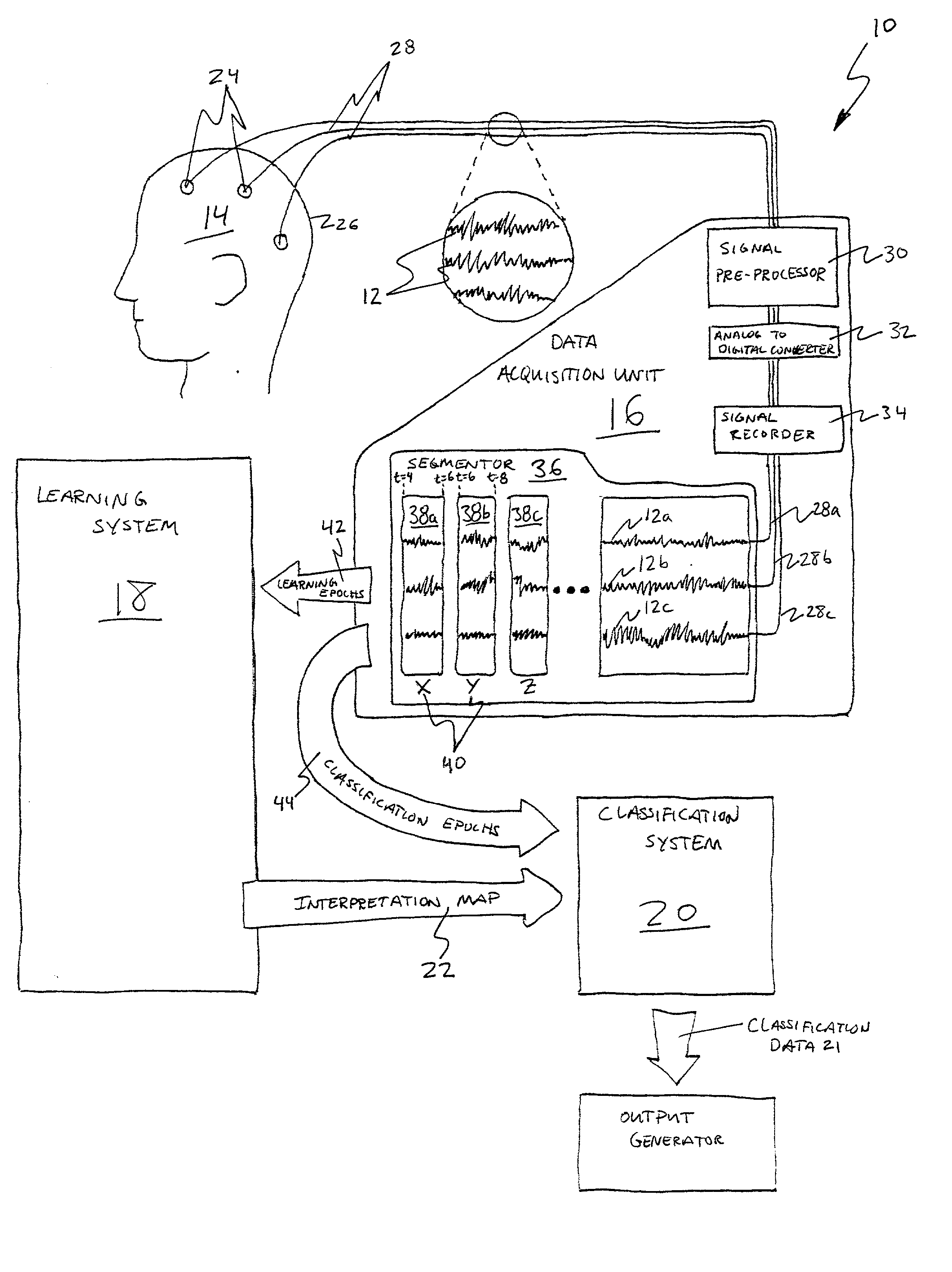
A method for assessing a condition of an organism having body waves corresponding to states of the organism. The method may include the step of recording signals corresponding to a body wave, output by a portion of the organism in a first state, to provide a first record. In a similar manner, signals may be recorded during a time period in which the organism is in a second state, to provide a second record. The first and second records, may be processed by applying feature expansion procedures thereto. The results of the feature expansion procedures may be evaluated to identify first selected feature expansion procedures effective to distinguish values of the first signals corresponding to the first state from values of the first signals corresponding to the second state.

Description

[0001] This application claims the benefit of U.S. Provisional Application No. 60 / 214,624, filed Jun. 28, 2000, and entitled CENTRAL NERVOUS SYSTEM AND CARDIO-VASCULAR DRUG PROFILING SYSTEMS and is a continuation-in-part of co-pending U.S. patent application Ser. No. 08 / 840,052, filed Apr. 24, 1997, and entitled SIGNAL INTERPRETATION ENGINE. The foregoing applications are hereby incorporated herein by reference.[0002] 1. The Field of the Invention[0003] This invention relates to signal processing and, more particularly, to novel systems and methods for pattern recognition and data interpretation relative to monitoring and categorizing patterns for predictably quantifying and evaluating systems of an observed entity as they react to stimuli such as, for example, drug profiling.[0004] 2. The Background Art[0005] The nervous system is a complex network of tissue for carrying and transmitting signals from one part of a body to another. The nervous system can be divided into the central ...

Claims


Application Information

Patent Timeline
IPC IPC(8): A61B5/04A61B5/0476G06F17/00G06F19/00
CPCA61B5/04008A61B5/04012G06F19/3456G06F19/322G06F19/3443A61B5/0476A61B5/4094G16H10/60G16H50/70G16H20/10A61B5/245A61B5/316A61B5/369A61B5/372
Inventor COOK, DANIEL R.
Owner BRIGHT IDEAS
Learn More