Eureka AIR delivers breakthrough ideas for toughest innovation challenges, trusted by R&D personnel around the world.

Method to produce ultra-low friction carbon films

a carbon film, ultra-low friction technology, applied in the direction of instruments, record information storage, transportation and packaging, etc., can solve the problems of high frictional loss, severe wear damage on the initial mating surface, rough surface, etc., to achieve ultra-low friction and wear properties

Inactive Publication Date: 2002-04-11
UCHICAGO ARGONNE LLC
View PDF7 Cites 35 Cited by
  • Summary
  • Abstract
  • Description
  • Claims
  • Application Information

AI Technical Summary

Benefits of technology

[0011] It is an additional object of the invention to provide an improved method and article of manufacture of diamond-like carbon film exhibiting a molecular structure, as characterized by Fourier Transform Infrared (FTIR) Spectroscopy, providing ultra-low friction and wear properties.
[0012] It is still another object of the invention to provide a new method and article of manufacture of carbon film with an underlying silicon film, deposited on a substrate, with the film composite exhibiting ultra-low friction and wear properties.
[0013] It is also a further object of the invention to provide an improved method and article of manufacture of carbon film disposed on a substrate of one or more of steel, ceramic, plastic, polymers, semiconductors and other solid materials with the carbon film acting to protect the substrate from mechanical wear or chemical corrosion.
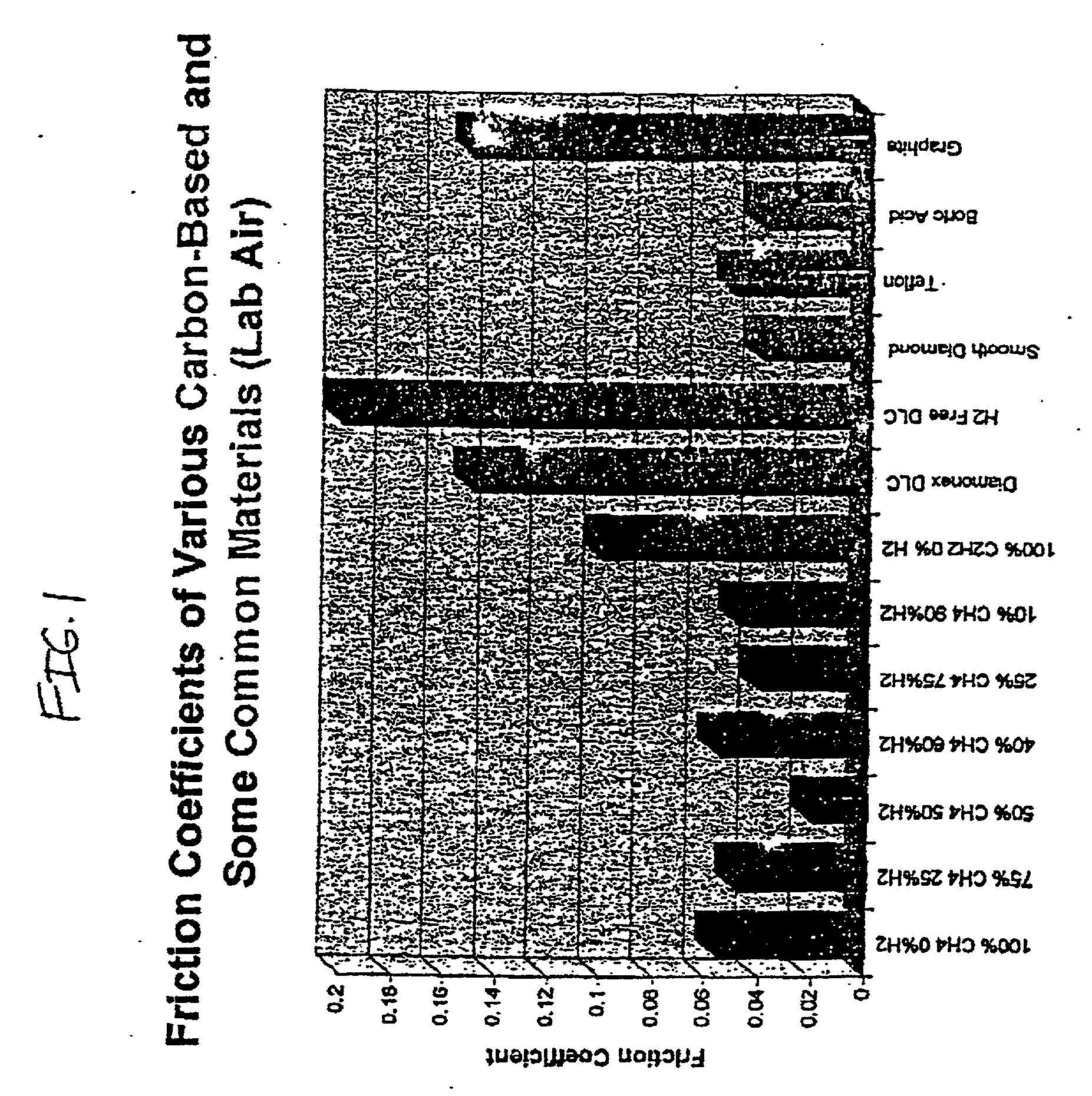
[0035] An important feature of the method and the resulting carbon films is the extremely low wear rates in dry N.sub.2 or Ar which are obtained when sliding against steel or ceramic counterfaces (i.e., about 10.sup.-10 to 5.times.10.sup.-11-mm.sup.3 / N.multidot.m; these values are 100 to 1000 times lower than those of the materials and coatings mentioned above). The wear rates of a well-lubricated steel surface is 10.sup.-7 mm.sup.3 / N.multidot.m, while that of an unlubricated steel surface is about 10.sup.-5 mm.sup.3 / N.multidot.m. The friction coefficients of the resulting carbon films are believed to be the lowest reported to date for a solid material, and its wear resistance is quite high. Examples of some wear ranges are shown in Tables 1 and 2 below for samples of the invention (and other materials) tested using conventional procedures based on the same testing methodology throughout (and described in the examples).1TABLE 1 Steel Ball Wear Rates (mm.sup.3 / N.m.) Sample Air N.sub.2 DLC7 (100% CH.sub.4) 2.08E-09 2.59E-09 DLC8 (25% H.sub.2 + 75% CH.sub.4) 1.13E-09 2.15E-09 DLC2 (50% H.sub.2 + 50% CH.sub.4) 1.50E-09 1.92E-10 DLC5 (60% H.sub.2 + 40% CH.sub.4) 2.29E-09 3.65E-09 DLC6 (75% H.sub.2 + 25% CH.sub.4) 4.14E-08 3.28E-10 DLC9 (90% H.sub.2 + 10% CH.sub.4) 4.20E-08 8.35E-10 DLC10 (100% C.sub.2H.sub.2) 3.45E-09 Severe wear DLC11 (90% H.sub.2 + 10% C.sub.2H.sub.4) 2.59E-09 3.27E-09 DLC3 (42% H.sub.2 + 58% CH.sub.4) 7.02E-09 2.01E-07 Uncoated H13 Steel 2.73E-05 4.50E-06 Diamonex 3.65E-09 Teer Coating LTD-UK 3.1E-09 8.3E-07 Tetrabond 1.07E-09 7.18E-07
[0038] A combination of extreme wear resistance and nearly frictionless nature makes the resulting film article potentially useful for a wide range of industrial. applications. The high degree of slipperiness and exceptional wear resistance of the new carbon film render it particularly adapted for reducing friction and wear under severe application conditions which exist in rolling, sliding and rotating mechanical devices such as seals, bearings, spindles, shafts, etc. Film deposition is done at nearly room temperature and at relatively high growth rates so that the physical and mechanical properties of the substrate materials are not adversely affected.

Problems solved by technology

Mechanically, these coating are very hard and abrasion resistant; however, they may contain large diamond grains and / or have non-diamond precursor materials between grains, and some of these surfaces can be very rough.
When used in machining or sliding wear applications, they cause high frictional losses and severe wear damage on the initial mating surfaces.
Certain ones of these coatings can become easily graphitized at elevated temperatures, and their wear properties can degrade.

Method used


Image

  • Method to produce ultra-low friction carbon films
  • Method to produce ultra-low friction carbon films
  • Method to produce ultra-low friction carbon films

Examples


example i

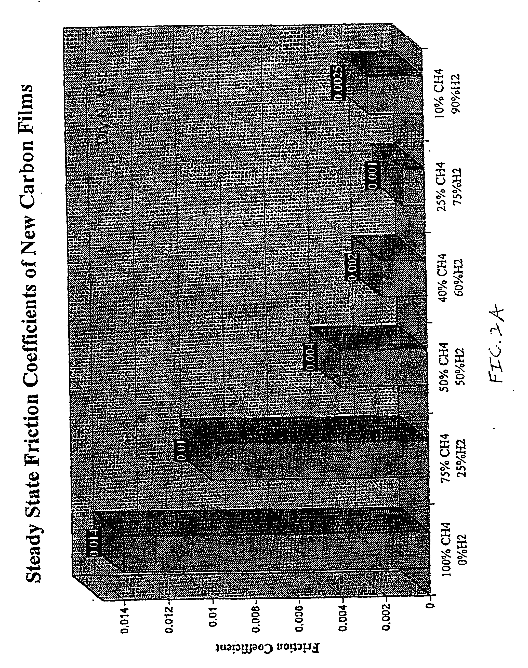
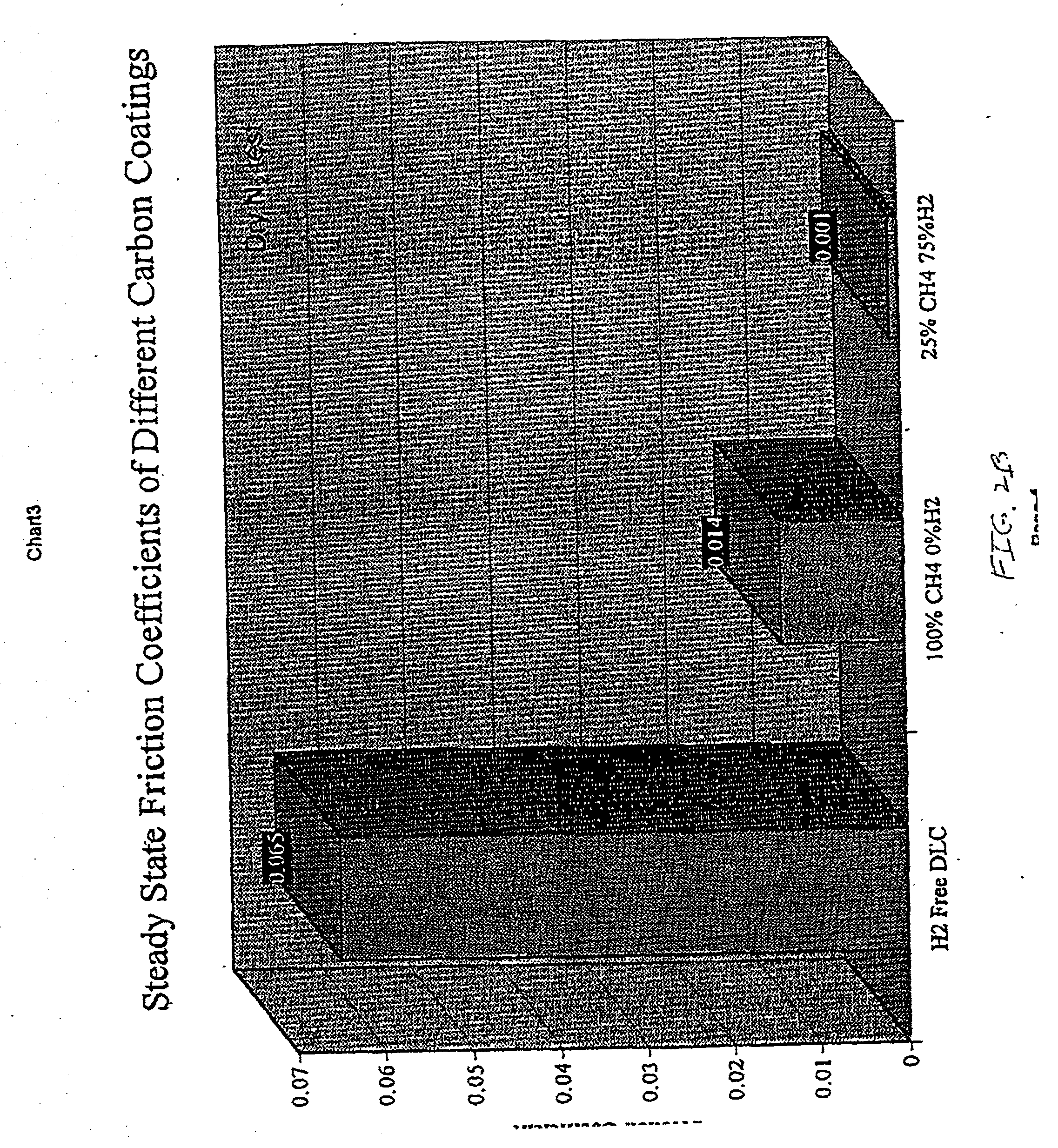
[0049] This example illustrates the friction and wear performance of carbon films derived from a hydrogen-methane gas discharge plasmas. Specifically, it shows that when methane is chosen as the carbon source, the friction coefficient of carbon films generally decreases with increasing amount of hydrogen in the plasma (however, see FIG. 2A showing an apparent minimum exists in friction coefficient). For the deposition of these carbon films, we used a commercially available plasma activated chemical vapor deposition system (Perkin Elmer 2400, from Perkin Elmer Corp.). Table 4 summarizes the range of methane / hydrogen used and resulting film properties measured in accordance with previously described well known techniques.

4TABLE 4 Effect of hydrogen on friction and wear properties of carbon films derived from methane (CH.sub.4). Test conditions: Load: 10 N, Speed, 0.5 m / s; Temperature, 22-23.degree. C.; test environment: dry N.sub.2. Friction Ball Wear C / H Ratio Carbon Films Grown in C...

example ii

[0051] In this example, acetylene was used as the carbon source. The film deposition parameters and friction and wear test conditions were kept the same as in Example I. Table 6 summarizes the results of friction and wear tests on acetylene-grown carbon films.

6TABLE 6 Effect of hydrogen on friction and wear properties of carbon films derived from acetylene (C.sub.2H.sub.2). Test conditions: Load: 10 N, Speed, 0.5 m / s; Temperature, 22-23.degree. C.; test environment: dry N.sub.2. Wear Rates of Friction Balls C / H Ratio Carbon Films Grown in Coefficient (mm.sup.3 / N .multidot. m) in Plasma 100% Acetylene -- 7.5 .times. 10.sup.-7 1 20% Hydrogen + 0.03 -- 0.8 80% Acetylene 25% Hydrogen + 0.027 6.86 .times. 10.sup.-8 0.75 75% Acetylene 50% Hydrogen + 0.0175 2.53 .times. 10.sup.-7 0.5 50% Acetylene 75% Hydrogen + 0.004 -- 0.25 25% Acetylene 90% Hydrogen + 0.003 .sup. 2.86 .times. 10.sup.-10 0.0833 10% Acetylene

example iii

[0052] In this example, ethane gas was used as the carbon source. The rest of the film deposition parameters and friction and wear test conditions were kept the same as in Example I. Table 7 summarizes the results of friction and wear tests on ethane-grown carbon films.

7TABLE 7 Effect of hydrogen on friction and wear properties of carbon films derived from ethane (C.sub.2H.sub.6). Test conditions: Load: 10 N, Speed, 0.5 m / s; Temperature, 22-23.degree. C.; test environment: dry N.sub.2. Wear Rates of Friction Balls C / H Ratio Carbon Films Grown in Coefficient (mm.sup.3 / N .multidot. m) in Plasma 100% Ethane -- 8.75 .times. 10.sup.-8 0.333 25% Hydrogen + 75% Ethane 0.015 2.71 .times. 10.sup.-8 0.3 50% Hydrogen + 50% Ethane 0.0073 3.34 .times. 10.sup.-8 0.25 90% Hydrogen + 10% Ethane 0.003 .sup. 2.86 .times. 10.sup.-10 0.0833


PUM

PropertyMeasurementUnit
Lengthaaaaaaaaaa
Lengthaaaaaaaaaa
Fractionaaaaaaaaaa

Abstract

A method and article of manufacture of amorphous diamond-like carbon. The method involves providing a substrate in a chamber, providing a mixture of a carbon containing gas and hydrogen gas with the mixture adjusted such that the atomic molar ratio of carbon to hydrogen is less than 0.3, including all carbon atoms and all hydrogen atoms in the mixture. A plasma is formed of the mixture and the amorphous diamond-like carbon film is deposited on the substrate. To achieve optimum bonding an intervening bonding layer, such as Si or SiO2, can be formed from SiH4 with or without oxidation of the layer formed.

Description

[0002] The subject invention is generally concerned with a method and article of manufacture of ultra-low friction carbon-based films. More particularly, the invention relates to a carbon containing film grown from a plasma containing about 25-95% hydrogen and about 75-5% of a carbon containing source gas such as methane, acetylene, ethylene, propane and ethane. A plasma activated chemical vapor deposition process is the preferred method but high quality carbon films can also be obtained by magnetron sputtering, ion plating, laser ablation, ion-beam assisted deposition, arc-physical vapor deposition and other vapor deposition processes which take advantage of the use of particular ratios of hydrogen to carbon atoms in the starting gaseous mixture.[0003] A large variety of diamond, diamond-like and amorphous carbon firms have been developed for use in applications requiring resistance to mechanical wear, abrasion and corrosive chemical conditions. Some of the carbon-based coatings, s...

Claims


Application Information

Patent Timeline
IPC IPC(8): C23C16/02C23C16/26
CPCC23C16/029Y10T428/30Y10T428/265C23C16/26
Inventor ERDEMIR, ALIFENSKE, GEORGE R.ERYILMAZ, OSMAN LEVENTLEE, RICHARD H.
Owner UCHICAGO ARGONNE LLC
Why Eureka
Eureka Blog
Learn More