Eureka AIR delivers breakthrough ideas for toughest innovation challenges, trusted by R&D personnel around the world.

Dual-mode microwave filter

a dual-mode microwave filter and filter technology, applied in the direction of waveguides, resonators, line-transmission, etc., can solve the problems of requiring the outlet multiplexer for satellites based on dual-mode filters in the form of circular waveguides still requires a great deal of design time and high cost, so as to achieve simple design, easy simulation, and suitable

Inactive Publication Date: 2002-02-28
EUROPEAN SPACE AGENCY
View PDF0 Cites 48 Cited by
  • Summary
  • Abstract
  • Description
  • Claims
  • Application Information

AI Technical Summary

Benefits of technology

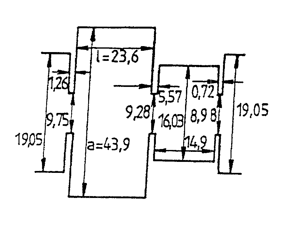
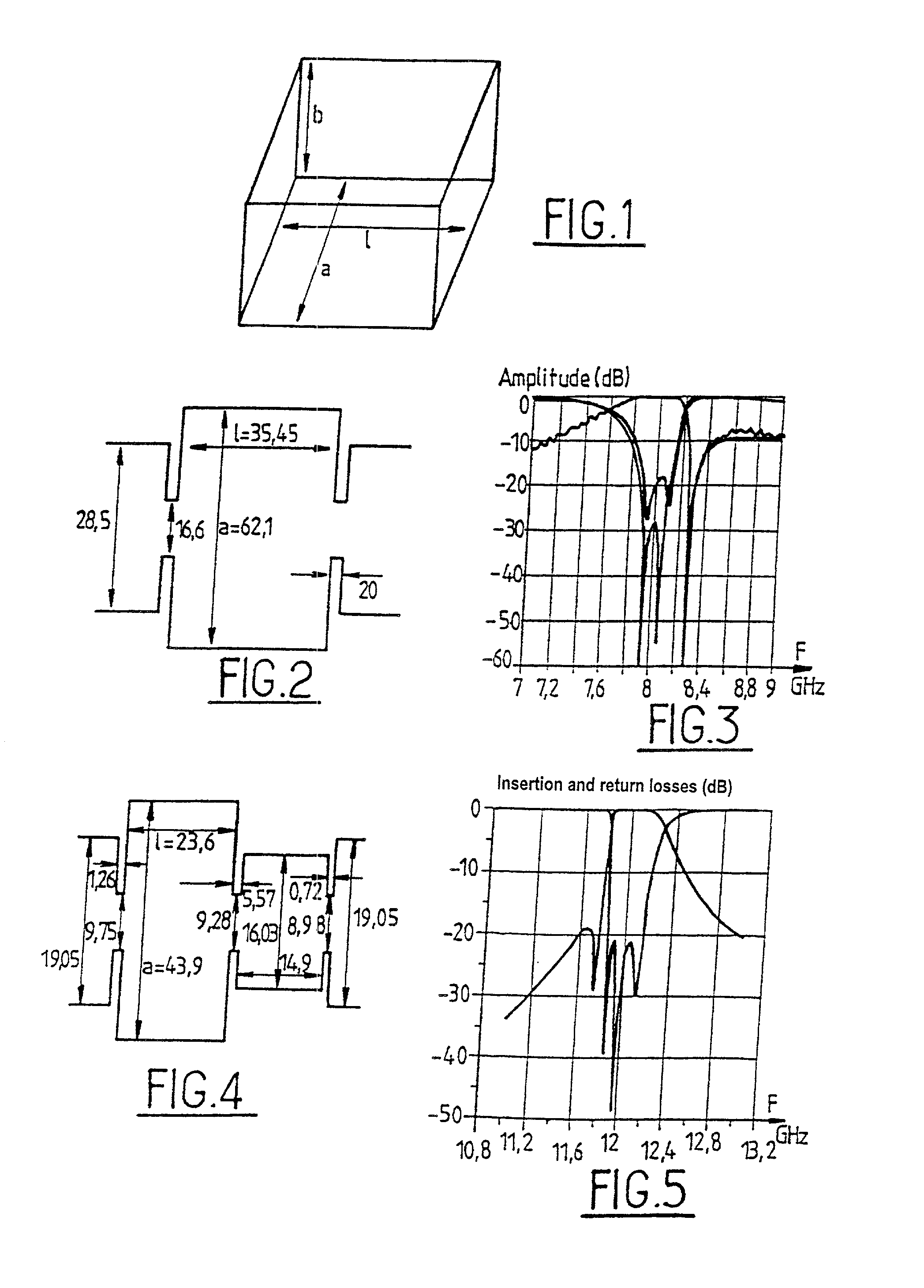
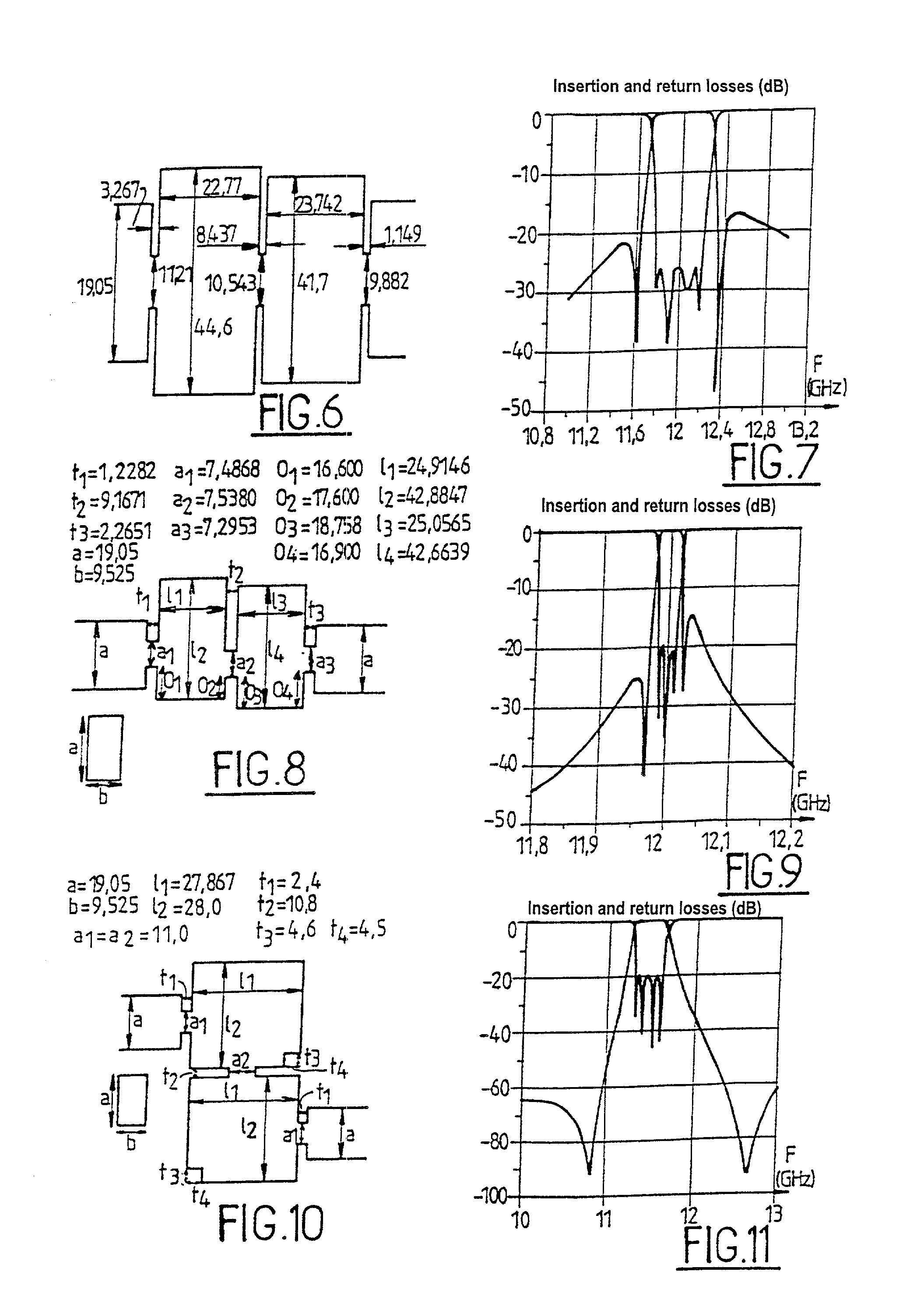
[0010] An object of the present invention is to provide a dual-mode microwave filter which presents the advantages of being simple to design and / or easy to simulate its electromagnetic waves and / or suitable for being manufactured by a method that is simple and low cost.
[0012] Given that use is made only of inductive discontinuities in rectangular waveguides, analysis and optimization can be performed in a manner that is much more accurate and efficient than with conventional implementations based on circular waveguides.
[0014] Another advantage is that the required filter structure is very simple and very suitable for high precision manufacture at low cost, thereby reducing the total cost of development and manufacture in highly significant manner.

Problems solved by technology

Such filters are capable of presenting filter transfer functions that are very complex and selective.
In addition, because of interactions between coupling irises and adjustment screws, it is necessary to devote considerable experimental effort in order to dimension coupling irises properly.
Although all of the studies mentioned above have significantly advanced the state of the art in this field, it nevertheless remains that making outlet multiplexers for satellites that are based on dual-mode filters in the form of circular waveguides still requires a great deal of design time and high cost.
The first is that even if the computer-assisted design (CAD) tools that have been developed are indeed practical for designing simple filters, they are not completely suited to designing complex multiplexers having a large number of channels, e.g. 10 to 20.
The second aspect is that the required geometry can have shapes that are very complex, and as a result it is very difficult to make such elements physically with the required precision which is generally better than or equal to 2 micrometers (.mu.m) to 5 .mu.m, depending on the electrical specifications.

Method used


Image

  • Dual-mode microwave filter
  • Dual-mode microwave filter
  • Dual-mode microwave filter

Examples


Embodiment Construction

[0034] A resonator forming a dual-mode filter in the form of a circular waveguide uses two degenerate TE.sub.1,1,n modes with electric fields that rotate with a phase offset of 90.degree.. By using dual-mode implementation, a single resonator can produce two independent electrical resonances. By connecting two of these resonators in series, it is thus possible to introduce cross-couplings between the four independent resonances so as to obtain complex filter functions.

[0035] The adjustment or tuning between the two independent resonances of each resonator is performed by means of an adjustment or tuning screw disposed at 45.degree. relative to the electric fields of the two resonances, with inter-resonator coupling, and with coupling between the inlet and the outlet being performed by coupling irises. The individual resonances are frequency adjusted using additional adjustment screws which extend parallel to the specific dual-mode electric field that is to be adjusted. All of these ...


PUM


Abstract

The invention provides a dual-mode microwave filter, comprising a rectangular resonator of length l, height b, and width a operating in two distinct modes (m, 0, n) and (p, 0, q) from a single family of modes and presenting the same direction as the E field, and wherein coupling and mode excitation discontinuities are inductive and in the same direction.

Description

[0001] The present invention relates to a dual-mode microwave filter for a waveguide intended, for example, for applications in telecommunications satellites. Such filters are capable of presenting filter transfer functions that are very complex and selective.[0002] In the commonest implementation, resonators are used in the form of circular waveguides, together with coupling irises of complex shapes, and each cavity needs to be adjusted manually using a minimum of three adjustment screws.[0003] Dual-mode filters for circular or elliptical waveguides are commonly used in the inlet / outlet networks of communications satellites, and their basic characteristics are well known, e.g. from the article by A. E. Williams "A four-cavity elliptic waveguide filter", published in IEEE Transactions on Microwave Theory & Techniques, Vol. 1.8, (MTT-18), December 1970, pp. 1109-1114, and also in the article by A. E. Atia et al., entitled "Narrow bandpass waveguide filters", published in IEEE Transac...

Claims


Application Information

Patent Timeline
IPC IPC(8): H01P1/208
CPCH01P1/2082
Inventor GUGLIELMI, MARCOJARRY, PIERREKERHERVE, ERIC
Owner EUROPEAN SPACE AGENCY
Why Eureka
Eureka Blog
Learn More