
Method for improving mechanical strength in micro electro mechanical systems and devices produced thereof

a mechanical system and micro-electrostrictive technology, applied in microstructural technology, piezoelectric/electrostrictive devices, renewable energy products, etc., can solve the problems of imposing restrictions on meeting simultaneously both types of specifications, affecting the mechanical strength of the planar element, and causing a large yield loss, so as to improve the mechanical strength of the planar element, and improve the effect of bending or lateral forces

Inactive Publication Date: 2002-01-24
INTERUNIVERSITAIR MICRO ELECTRONICS CENT (IMEC VZW)
View PDF0 Cites 26 Cited by
  • Summary
  • Abstract
  • Description
  • Claims
  • Application Information

AI Technical Summary

Benefits of technology

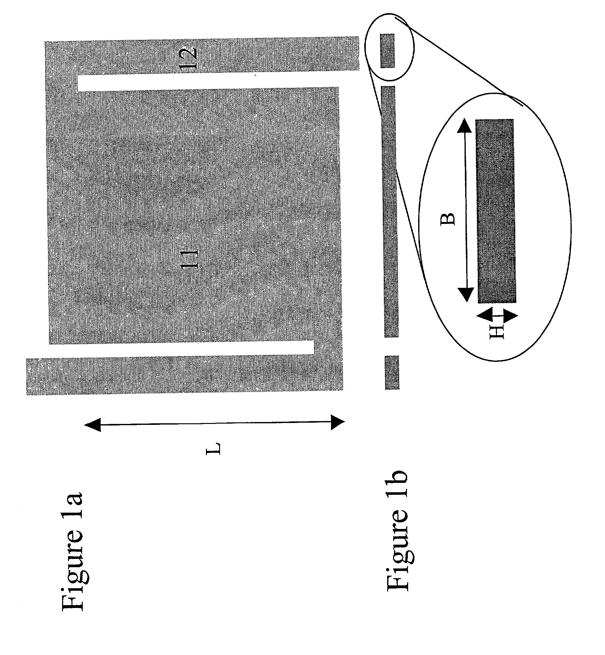
[0009] One aspect the present invention aims to improve the mechanical stability of the MEMS devices. The improved mechanical strength can lead to higher production and packaging yield. It can also improve the operation of MEMS devices that have moving elements. By introducing this method, the thickness of layers can be adapted to meet other technological specifications and still have sufficient mechanical strength. The improved mechanical strength can lead to higher production and packaging yield. The improvement in mechanical strength with respect to the device properties can be expressed in terms of a figure of merit M. In the finished MEMS device, layers may indeed not be fully supported by an underlying layer and hence lack mechanical strength.
[0010] Another aim of the present invention is to provide a device for sensing electromagnetic radiation with improved mechanical characteristics and device performance.
[0011] Another aim of the present invention is to obtain an infrared sensor with improved mechanical characteristics and device performance. An advantage of this device is that the thickness of the layer, e.g. the sensing layer, can be adapted to have the maximum temperature sensitivity thanks to a minimal thermal conductance possible for a given layout or material choice. Another advantage of such a device is that the time constant of this thermal sensor is minimized to such a level that the device can be applied in fast thermal sensor camera applications. The improved mechanical strength allows using a minimal layout of the devices so the thermal sensor can be used in an array-type of circuitry. The improvement in mechanical strength with respect to the device properties can be expressed in terms of a figure of merit M. In the present application, the term "layer" should be understood as a stack of at least one layer. U- or I-shaped layer means that a part of the cross section of this layer has a U- or I-shaped profile. Generally, a structure in a MEMS device which provides a three-dimensional shape to a part of a MEMS device will be called a "microstructure" and insofar as it improves the mechanical properties of the device, e.g. its rigidity, it will be called a "rigidizing microstructure." In one aspect of the invention, MEMS devices with improved mechanical characteristics are provided.
[0013] In one embodiment of the invention, the resistance of layers in MEMS devices to bending, lateral or torsion forces, having a static or dynamic nature, is increased by providing these layers with one or more rigidizing microstructures. The term "rigidized" is well known in the mechanical arts and refers to providing structures such as corrugations to improve the mechanical properties of a sheet material, especially improving the resistance to bending and / or deformation. "Internally rigidized" refers to a form of rigidizing in which the reinforcing structures are contained within the confines of a layer, i.e., it does not involve the application of external rigidizing elements which extend beyond the edges of the layer concerned. Preferred microstructures are those similar to an I- or U-profile or a combination of such profiles in a two-dimensional array instead of using the conventional rectangular profiles. In the finished MEMS device, layers may indeed not be fully supported by an underlying layer and hence lack mechanical strength. At least a part of non-fully supported layer is a membrane, that is a thin layer of such an extent that it has a recognizable and useful area. Such a membrane may be come in a variety of shapes including circular, elliptical, oval, quadratic, a parallelepiped or a similar 2-D shape overall. The membrane is attached to a substrate by a support system.
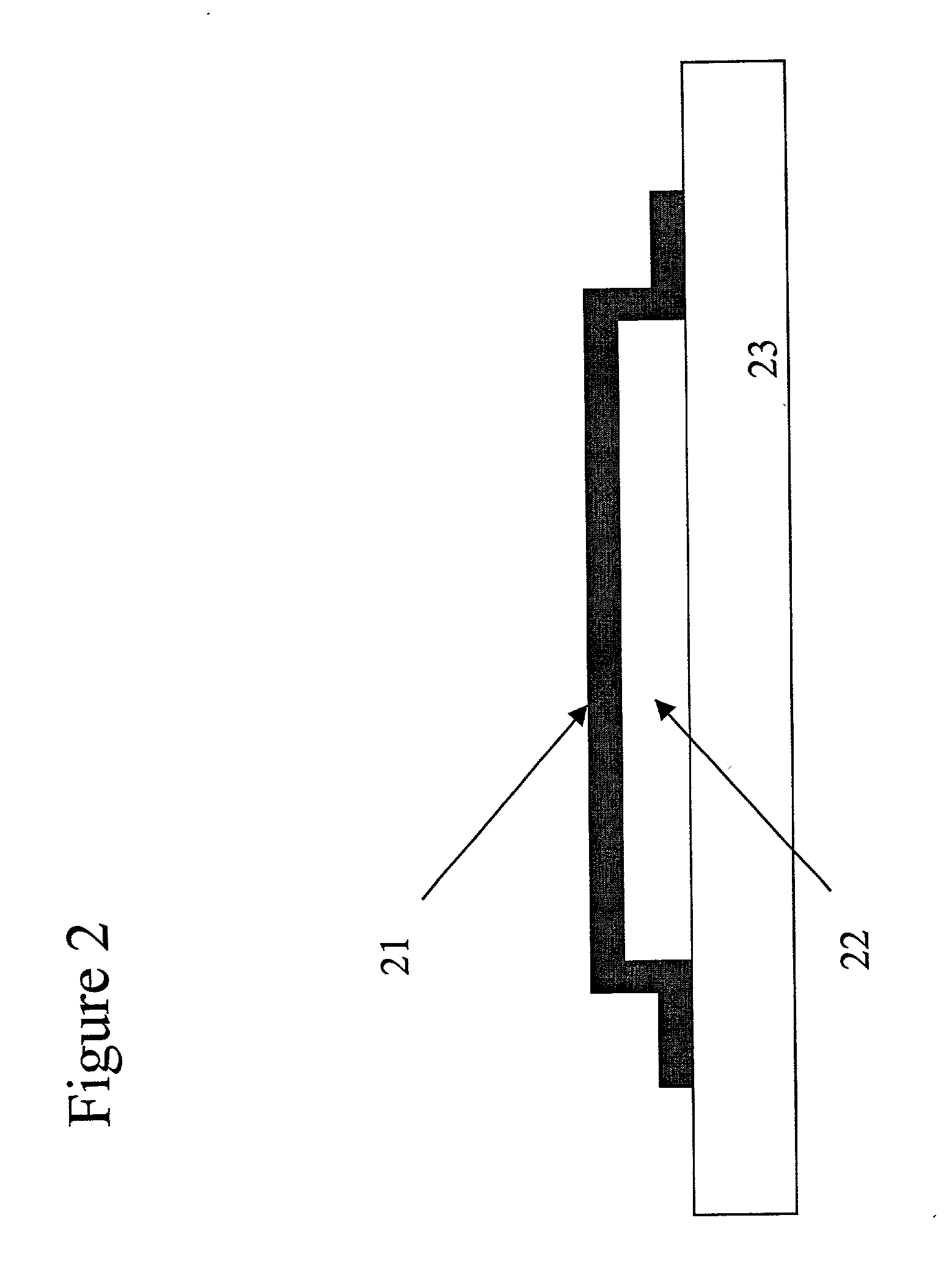
[0017] In another embodiment of the invention a MEMS device is disclosed comprising a planar element or membrane, having an improved mechanical strength.
[0020] In another aspect of the invention, a thermal sensor, e.g. infra-red sensor, having a membrane, especially a membrane which supports or is integral with a sensing element of the sensor, is provided having improved mechanical strength to bending or lateral forces, by applying a microstructure in the membrane e.g. an I or U-shaped layer or a combination thereof. whereby The improved mechanical strength of the planar element allows the use of thinner layers and results in a faster read-out of the sensor.

Problems solved by technology

The strong interaction between the transducing and mechanical properties of these systems often imposes restrictions on meeting simultaneously both types of specifications.
The very last process step, being the removal of the sacrificial layer between the sensing element and the underlying substrate thereby creating the aforementioned gap, is critical and difficult.
Due to a general problem in surface micromachining, called sticking, the removal of such a sacrificial layer causes a lot of yield loss.
Once the sensing element reaches the substrate, strong bonding forces between this sensing element and the substrate along with the mechanical weakness of the supporting beams prevent the sensing element from returning to its original position.
Once the sensing element touches the substrate, the device has a large thermal conductance to the substrate and is useless as a bolometer.
Making the supporting beams thinner will improve the thermal insulation of the sensing element but turns out to make the problem of sticking more severe, resulting in yield loss during processing and packaging of such devices.
However, this structure is obtained at the expense of additional, time consuming, process steps.
These process steps cannot be done in the course of producing the gimbal, but require separate processing, followed by assembly.
The technique disclosed is very complex and time consuming and does not allow waferscale processing.

Method used


Image

  • Method for improving mechanical strength in micro electro mechanical systems and devices produced thereof
  • Method for improving mechanical strength in micro electro mechanical systems and devices produced thereof
  • Method for improving mechanical strength in micro electro mechanical systems and devices produced thereof

Examples


Embodiment Construction

[0040] For the purpose of teaching of the invention, preferred embodiments of the method are described in the sequel. The present invention will be described with respect to certain embodiments and drawings. It will however be apparent to the person skilled in the art that other alternatives and equivalents or embodiments of the invention or combinations thereof can be conceived and reduced to practice without departing from the true spirit of the invention as defined in the attached claims. Dimensions are given in micrometers, using the symbols micron or .mu.m, or in square micrometer, using the symbol .mu.m.sup.2.

[0041] The mechanical stability of the MEMS devices needs to be improved because this improvement can result in larger production and packaging yield, as the device can withstand mechanical shocks and loads better, for example during handling. Mechanical stability can also lead to a better operation of the device, as the device has a higher resistance to external mechanic...


PUM


Abstract

Structures and methods are disclosed to produce mechanical strength in Micro Electro Mechanical Systems by increasing the moment of inertia of some of the composing elements. In one aspect, a thermal sensor with improved mechanical strength, thermal insulation and time constant is achieved. Moreover, the current method and apparatus is advantageous in terms of process time and process cost, particularly in the area of lithographic patterning.

Description

REFERENCE TO RELATED APPLICATIONS[0001] The current patent application is a continuation-in-part of U.S. patent application Ser. No. 09 / 702,501 entitled "Method Of Fabrication Of An Infrared Radiation Detector And Infrared Detector Device," pending, which is a continuation of U.S. patent application Ser. No. 09 / 049,797 now U.S. Pat. No. 6,194,722. This application further claims priority benefits to European Patent Application Number EP 97870044.1 filed on Mar. 28, 1997 and to European Patent Application Number EP 002011083.3 filed on Mar. 24, 2000. This application claims priority benefits to U.S. Provisional Application Ser. No. 60 / 171,976 filed on Dec. 22, 1999. This application incorporates by reference U.S. Pat. No. 6,194,722 in its entirety. This application further incorporates by reference European Patent Application Number EP 97870044.1 filed on Mar. 28, 1997 and European Patent Application Number EP 002011083.3 filed on Mar. 24, 2000 in their entirety. This application fur...

Claims


Application Information

Patent Timeline
IPC IPC(8): B81B3/00G01J5/10G01J5/20H01L31/09H01L31/18
CPCB81B3/0072B81B2203/0109G01J5/10G01J5/20H01L31/09H01L31/1804Y02E10/547Y02P70/521Y02P70/50G01J5/024G01J5/023
Inventor MOOR, PIET DEHOOF, CHRIS VAN
Owner INTERUNIVERSITAIR MICRO ELECTRONICS CENT (IMEC VZW)
Learn More