Microwell device and method of manufacturing the same

Active Publication Date: 2022-11-08
ACAD SINIC
View PDF11 Cites 0 Cited by
  • Summary
  • Abstract
  • Description
  • Claims
  • Application Information

AI Technical Summary

Benefits of technology

[0007]In response to the above-referenced technical inadequacies, the present disclosure provides a microwell device array, which can be applied to 3D cell culture, effectively prevents cells from flowing out of the cell culture well, and can provide for long-term study and high-throughput analysis of isolated single cells.
[0026]One of the advantages of the present disclosure is that, the microwell device and the method of manufacturing the same of the present disclosure can make the cells experiencing 3D microenvironment, reduce cell loss, and make it easy for the experimenters to operate through the technical solution of “each of the microwells includes a cavity being recessed on the substrate and an opening, and wherein the diameter of the opening is smaller than the largest inner diameter of the cavity” and “the plurality of microwells are curved”.

Problems solved by technology

Some 3D cell culture are hemi-spherical which may be achieve a better effect than cylindrical 3D culture s. However, during operation (for instance, when changing the cell medium and when rinsing), the cells may easily slip out of the cell culture well, which will result in the loss of experimental data and burden on the operator.

Method used


Image

  • Microwell device and method of manufacturing the same
  • Microwell device and method of manufacturing the same
  • Microwell device and method of manufacturing the same

Examples


first embodiment

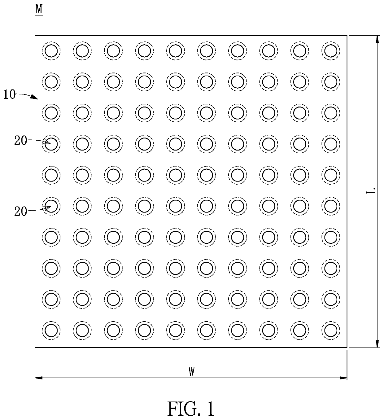
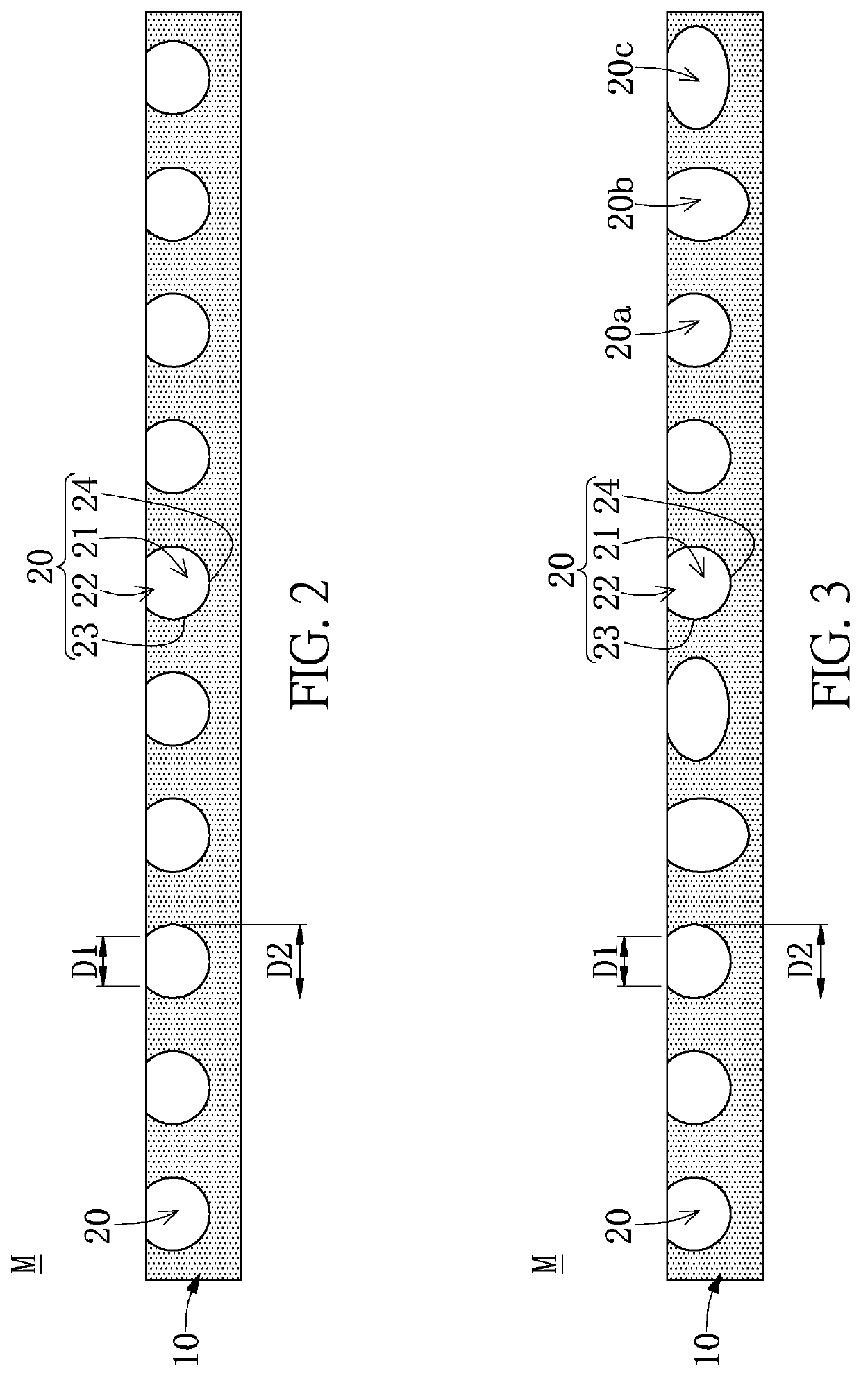
[0051]Referring to FIG. 1 to FIG. 2, a first embodiment of the present disclosure provides a microwell device M including a substrate 10 and a plurality of microwells 20 formed on the substrate 10. Each of the microwells 20 includes a cavity 21 being recessed on the substrate 10 and an opening 22, and wherein the diameter D1 of the opening 22 is smaller than the largest inner diameter D2 of the cavity 21. In addition, the plurality of microwells 20 are curved.

[0052]Further, the material of the substrate 10 can, but not limited to being, poly(acrylamide), polydimethylsiloxane, poly(lactic-co-glycolic acid), gelatin, silicone, polydimethylsiloxane, polyethylene, polystyrene, polyolefin, polyolefin copolymers, polycarbonate, ethylene vinyl acetate, polypropylene, polysulfone, polytetrafluoroethylene (PTFE), compatible fluoropolymer, or poly(styrene-butadiene-styrene).

[0053]Referring to FIG. 1, the length L of the substrate 10 of the device M of the present disclosure can be 10 mm to 30...

second embodiment

[0057]Referring to FIG. 7 to FIG. 13, a second embodiment of the present disclosure provides a method for manufacturing a microwell device M, which at least includes step S100 to step S110. Firstly, in step S100, a microcolumn array N having a plurality of microcolumns 70 is produced from a first template by photolithography or soft lithography. In addition, the microcolumn array N can be made of polydimethylsiloxane (PDMS). In step S102, after a lift-off layer 80 [1% bovine serum albumin (BSA) in phosphate-buffered saline (PBS)] is coated on the microcolumns array N, a plurality of glass microspheres 90 are disposed on each of the plurality of the microcolumns 70 of the microcolumn array N (step S104). Next, in step S106, silicon (fast-curing silicone) is poured onto the microcolumn array N being disposed with the glass microspheres 90, after curing, the cured silicone is separated from the microcolumn array N and the glass microspheres 90 to form a second template K having a plura...

third embodiment

[0062]The Madin-Darby canine kidney (MDCK) cells were cultured in the s of the microwell device (80 μm of the largest inner diameter) on an orbital shaker. The microwell device was perturbed sequentially using four 30 minutes sessions using different parameters: (1) at 100 rpm with s facing upward; (2) at 100 rpm with microwells facing downward; (3) at 200 rpm with microwells facing upward; and (4) at 200 rpm with microwells facing downward. Results from after step (1) and (4) are shown in FIG. 14 and FIG. 15, respectively. Over the 2 hours perturbation, only one microwell of MDCK cell (black border in FIG. 15) was lost out of 32 microwells (dashed box in FIGS. 14 and 15). Therefore, this embodiment shows that the microwells of the microwell device of the present disclosure can prevent cells from slipping out of the microwells.


PUM

PropertyMeasurementUnit
inner diameteraaaaaaaaaa
diameteraaaaaaaaaa
widthaaaaaaaaaa

Abstract

A microwell device and a method of manufacturing the same are provided. The microwell device includes a substrate and a plurality of microwells formed on the substrate. In addition, each of the microwells includes a cavity being recessed on the substrate and an opening, and the diameter of the opening is smaller than the largest inner diameter of the cavity. Furthermore, the microwells are curved.

Description

CROSS-REFERENCE TO RELATED PATENT APPLICATION[0001]This application claims priority from the U.S. Provisional Patent Application Ser. No. 62 / 835,009 filed Apr. 17, 2019, which application is incorporated herein by reference in its entirety.[0002]Some references, which may include patents, patent applications and various publications, may be cited and discussed in the description of this disclosure. The citation and / or discussion of such references is provided merely to clarify the description of the present disclosure and is not an admission that any such reference is “prior art” to the disclosure described herein. All references cited and discussed in this specification are incorporated herein by reference in their entireties and to the same extent as if each reference was individually incorporated by reference.FIELD OF THE DISCLOSURE[0003]The present disclosure relates to a cell culture device, and more particularly to a microwell device and a method of manufacturing the same.BACK...

Claims


Application Information

Patent Timeline
Patent Type & Authority Patents(United States)
IPC IPC(8): C12M1/32C12M1/00B01L3/00C12N5/00
CPCC12M23/12B01L3/5085C12M23/20C12M23/38B01L2200/12B01L2300/0819B01L2300/0829B01L2300/0858C12N5/0062
Inventor LIN, KENG-HUIHUANG, CHENG-KUANG
Owner ACAD SINIC
Why Eureka
Try Eureka