
Voltage regulator and bandgap voltage reference with novel start-up circuit and seamless voltage reference switch over for PSR enhancement

a voltage regulator and bandgap technology, applied in the direction of electric variable regulation, process and machine control, instruments, etc., can solve the problems of adding cost and size to the overall solution, external components, and still having some noise (ripples) coupled from supply noise, etc., to achieve smooth output voltage, high psrs, and high psrs

Active Publication Date: 2022-09-06
VIDATRONIC
View PDF6 Cites 0 Cited by
  • Summary
  • Abstract
  • Description
  • Claims
  • Application Information

AI Technical Summary

Benefits of technology

The solution achieves very high PSR without large filters, ensures smooth startup and operation, and reduces power consumption by optimizing voltage reference management, resulting in high-performance and cost-effective linear voltage regulators.

Problems solved by technology

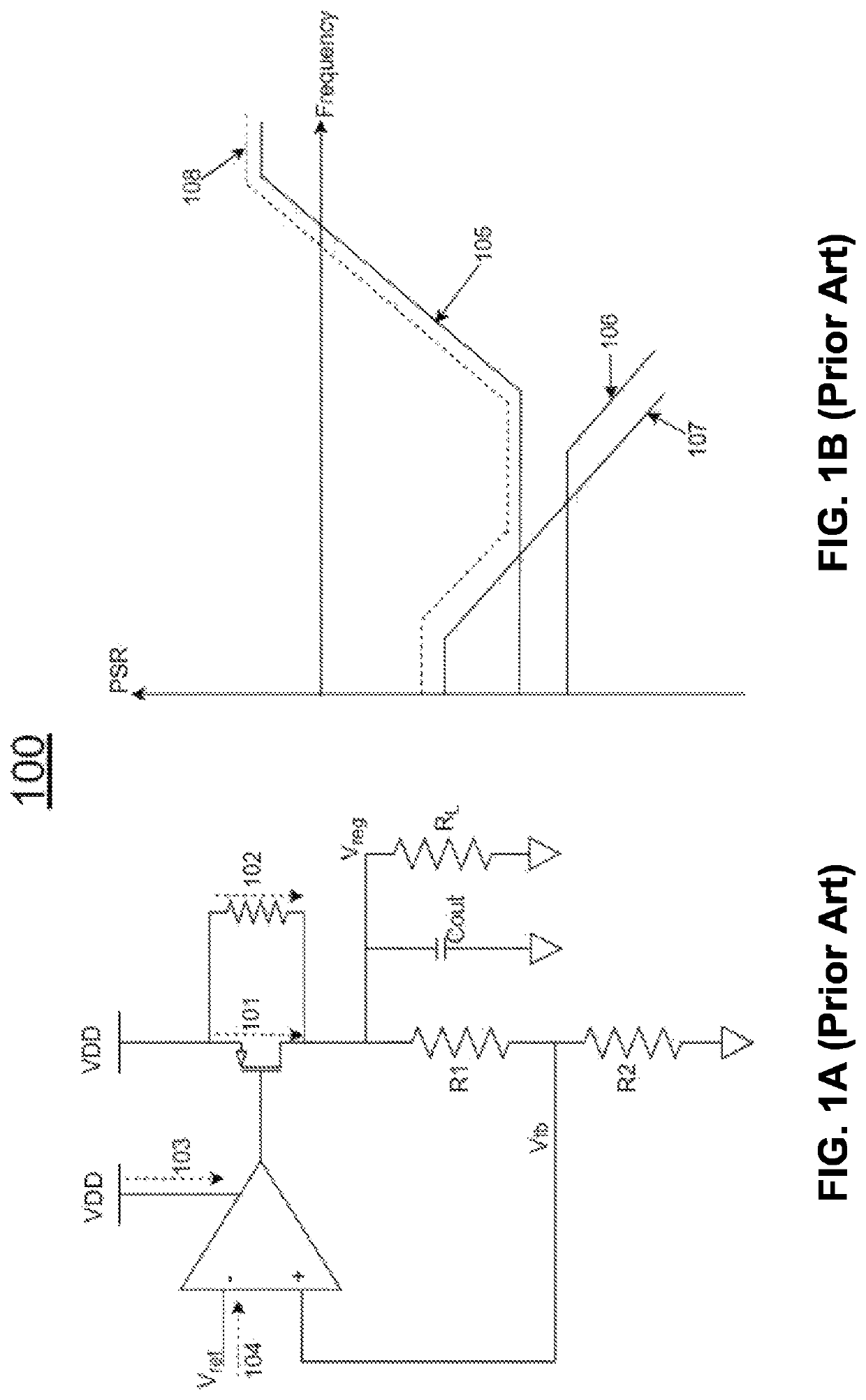
While the LDO output is primarily only a function of the voltage reference, it still has some noise (ripples) coupled from the supply noise.
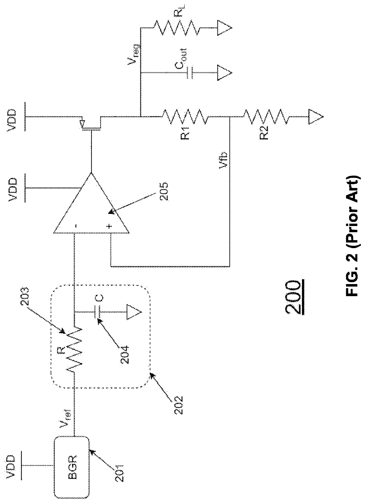
One drawback of this method is that the values of R (203) and C (204) are very large in order to have the filter's cutoff frequency at low frequencies.
This requires large silicon area to implement the Resistor and the Capacitor on-die, or else external components on the Printed Circuit Board (PCB) must be used (the external components add cost and size to the overall solution).
A second drawback is the long time that it takes for the voltage reference to settle, which can be a detriment in some systems.
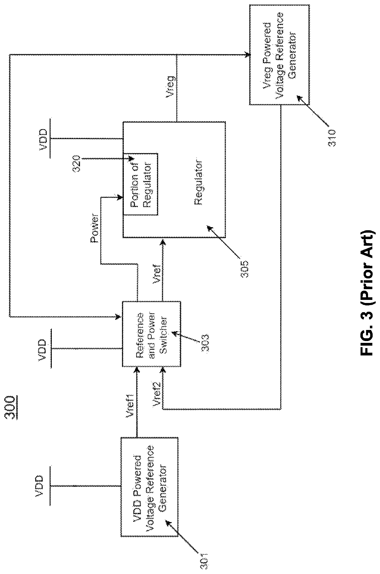
First, there is a risk that there could be a drop in the voltage reference going to the linear voltage regulator block LDO (305) at the time of switching from Vref1 to Vref2 (unless a smooth switching scheme is used), causing the output of the regulator (Vreg) to also drop.
A second disadvantage of the architecture is that it needs to switch both the voltage reference going to the linear voltage regulator (305) (from Vref1 to Vref2) and the supply of a portion of the regulator (320) (from VDD to Vreg) at the same time.
This could introduce additional droops or glitches in the output.
A third disadvantage is that the VDD power to the first voltage reference generator (301) is not shut down even after switching, wasting quiescent power.
A fourth disadvantage is that the system has only one linear voltage regulator (305) generating one Vreg, which will be used as a power supply for the Vreg powered second voltage reference generator (310) and other loads.
This can cause a problem when one of the other loads taking its supply from (Vreg) is a switching load causing some spikes and variations in Vreg, which in turn can affect the Vreg powered second voltage reference generator output (Vref2).
A fifth disadvantage is that the linear voltage regulator (305) will need to be designed with a large pass transistor to support all the loads of the circuit and this leads to bad PSR of that regulator (compared to other regulators with small pass transistors).
A sixth limitation in this architecture is that the (Vref1) and (Vref2) must have equal values for correct operation, because if (Vref2) is different from (Vref1), the output of the linear voltage regulator (305) (Vreg) will experience a sudden change at the moment of switching between the voltage references.
A seventh disadvantage is that there is no soft startup circuit for the linear voltage regulator (305), which may lead to some overshoots at the output of the regulator (305) Vreg at the startup, which may affect Vref2.

Method used


Image

  • Voltage regulator and bandgap voltage reference with novel start-up circuit and seamless voltage reference switch over for PSR enhancement
  • Voltage regulator and bandgap voltage reference with novel start-up circuit and seamless voltage reference switch over for PSR enhancement
  • Voltage regulator and bandgap voltage reference with novel start-up circuit and seamless voltage reference switch over for PSR enhancement

Examples


Embodiment Construction

[0027]Aspects of the present invention are shown in the above-identified drawings and are described below. In the description, like or identical reference numerals are used to identify common or similar elements. The drawings are not necessarily to scale and certain features may be shown exaggerated in scale or in schematic in the interest of clarity and conciseness.

[0028]Embodiments of the invention relate to linear voltage regulators that have smooth outputs and high PSRs, without using a large filter or other external components. In the following description, embodiments of the invention will be illustrated with specific examples. However, one skilled in the art would appreciate that other modifications and variations are possible without departing from the scope of the invention.

[0029]As shown in FIG. 4A, a voltage regulation loop (40) in accordance with embodiments of the invention comprises: a reference voltage generation block (41), a soft startup circuit for LDO (42), and a ...


PUM

PropertyMeasurementUnit
bandgap voltageaaaaaaaaaa
voltageaaaaaaaaaa
temperatureaaaaaaaaaa

Abstract

A voltage regulation loop includes a voltage reference generation block that includes a bandgap voltage reference circuit; a linear voltage regulator block that includes a first and second linear voltage regulators, wherein the first linear voltage regulator provides a first regulated power supply to the bandgap voltage reference circuit in the voltage reference generation block, and the second linear voltage regulator provides a second regulated power supply to a load; and a soft startup circuit connected between the voltage reference generation block and the linear voltage regulator block, wherein a selector functions with a control block to output a selected voltage reference to pass to the soft startup circuit, wherein the soft startup circuit smooths the selected voltage reference and produces a smoothed voltage reference to pass to the linear voltage regulator block to prevent overshoots at startup.

Description

BACKGROUND[0001]A linear low-dropout voltage regulator (LDO) is a circuit that converts an unregulated DC supply into a well-regulated one, always using a closed loop control and a clean voltage reference that is usually independent of the temperature, process and supply variations. While the LDO output is primarily only a function of the voltage reference, it still has some noise (ripples) coupled from the supply noise. That is why the power supply rejection (PSR) is an important specification for linear voltage regulators. The PSR is a measure of how well the LDO rejects the supply noise (ripples), in order to have a well-regulated output that is not affected by the supply variations or noise.[0002]FIG. 1A shows a schematic block level diagram of a prior art linear voltage regulator (100). It illustrates the possible paths that couple the supply noise (ripples) to the output of the regulator affecting the PSR at its output. There are four paths for the noise coupled from the suppl...

Claims


Application Information

Patent Timeline
Patent Type & Authority Patents(United States)
IPC IPC(8): G05F1/46G05F3/16
CPCG05F1/46G05F3/16G05F1/468G05F3/30
Inventor HELMY ZAKY, BISHOY MILADVEERAVALLI RAGHUPATHY, ANAND
Owner VIDATRONIC
Learn More