A chain energy consumption device and its control method

An energy-consuming device and a control method technology, applied in the field of chain energy-consuming devices and control, can solve the problems of equipment safety operation hazards, DC transmission line voltage rise, large voltage and current rate of change, etc., to reduce shutdown Risk of overvoltage, increased operational reliability, cost and volume reduction effects

Active Publication Date: 2022-05-13
詹长江
View PDF5 Cites 0 Cited by
  • Summary
  • Abstract
  • Description
  • Claims
  • Application Information

AI Technical Summary

Problems solved by technology

The chain-type energy consumption device is mainly used in the application scenario of island power supply. If the power generation end is an inertial power source similar to wind power, when the power receiving end fails, the power will not be sent out, and the energy will be accumulated on the DC side, resulting in damage to the DC transmission line. The voltage rises, causing harm to the safe operation of the equipment
[0003] In the prior art, the method adopted is to directly connect the power semiconductor devices in series. When the DC voltage is too high, through the control of the power electronic device, a resistor is put in. The input of the resistor will reduce the DC voltage. When the energy consumption speed of the resistor exceeds the DC voltage The speed at which the side accumulates energy, the DC voltage will drop. At this time, turn off the resistance discharge circuit, the DC voltage will rise again, and repeatedly turn on and off the resistance branch, forming the effect of hysteresis control. The main problem of this method is The problem is that when turning off, it is difficult to ensure consistency because multiple power semiconductor switching devices are turned off at the same time. Once the shutdown is not synchronized, the slow-turning device or the fast-turning-off device will be damaged due to overvoltage; Moreover, the high-speed on and off state switching will also result in a large voltage and current change rate, resulting in magnetic field interference
In addition, in the prior art, each sub-module includes a large number of power semiconductor devices, and the cost is relatively high

Method used


Image

  • A chain energy consumption device and its control method
  • A chain energy consumption device and its control method
  • A chain energy consumption device and its control method

Examples


Embodiment Construction

[0039] The present invention will be further described below in conjunction with accompanying drawing.

[0040] In order to achieve the above object, the concrete scheme that the present invention adopts is as follows:

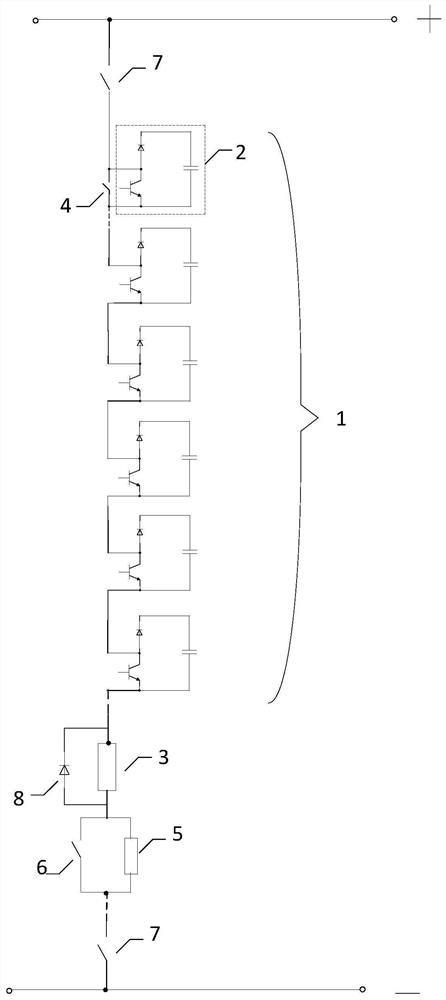
[0041] like figure 1 As shown, a chain type energy consumption device, the device is composed of an energy consumption branch 1 and an energy consumption resistor 3, the energy consumption branch is composed of at least one energy consumption sub-module 2 connected in series in the same direction, the series connection The first end of the energy dissipation resistor is connected to the high-potential electrode of the DC line; the energy dissipation resistor is centrally arranged and connected in series with the energy dissipation branch, one end of the energy dissipation resistor is connected to the tail end of the energy dissipation branch, and the other end is connected to the low potential electrode of the DC line. Electrode connection; the energy consump...


PUM


Abstract

The invention discloses a chain type energy consumption device. The device is composed of an energy consumption branch and an energy consumption resistor. The energy consumption branch is composed of at least one energy consumption sub-module connected in series in the same direction. The first end of the series connection is connected to the The high-potential electrode of the DC line is connected; the energy-dissipating resistor is arranged in series with the energy-consuming branch, and one end of the energy-dissipating resistor is connected to the tail end of the energy-consuming branch, and the other end is connected to the low-potential electrode of the DC line. The energy consumption sub-module is composed of a first power semiconductor switching device, a diode and a DC capacitor; the present invention also includes a control method for a chained energy consumption device. The power semiconductor switching device in the sub-module realizes DC voltage control, realizes flexible input and flexible withdrawal of energy-consuming resistors, and the device has high cost performance, high reliability, and is easy to implement.

Description

technical field [0001] The invention belongs to the technical field of high-power electric current conversion, and in particular relates to a chain type energy consumption device and a control method. Background technique [0002] In HVDC power transmission system, chain energy consumption device is a crucial equipment. The chain-type energy consumption device is mainly used in the application scenario of island power supply. If the power generation end is an inertial power source similar to wind power, when the power receiving end fails, the power will not be sent out, and the energy will be accumulated on the DC side, resulting in damage to the DC transmission line. The voltage rises, which will endanger the safe operation of the equipment. [0003] In the prior art, the method adopted is to directly connect the power semiconductor devices in series. When the DC voltage is too high, through the control of the power electronic device, a resistor is put in. The input of the...

Claims


Application Information

Patent Timeline
Patent Type & Authority Patents(China)
IPC IPC(8): H02J3/36
CPCH02J3/36H02J2003/365Y02E60/60
Inventor 詹长江王宇陈松林沈全荣刘为群
Owner 詹长江
Why Eureka
Try Eureka