
Information handling system dynamic foot for adaptive thermal management

a technology of information handling and dynamic foot, applied in the field of portable information handling systems, can solve the problems of reducing thermal transfer efficiency, affecting the operation of portable computers, and inability to fully use such processing components, so as to reduce the skin temperature of the system, improve thermal rejection, and reduce the cost

Active Publication Date: 2022-09-06
DELL PROD LP
View PDF13 Cites 0 Cited by
  • Summary
  • Abstract
  • Description
  • Claims
  • Application Information

AI Technical Summary

Benefits of technology

The dynamic foot system enhances airflow by 34% and reduces system skin temperature by 6 degrees Celsius, enabling higher power consumption without exceeding thermal constraints, while retracting to maintain a sleek profile.

Problems solved by technology

Although a small profile housing can include powerful processing components, typically the ability to fully use such processing components is limited by the thermal energy generated as a byproduct of power dissipation by the processing components.
In portable information handling systems having active thermal management, such as a cooling fan that intakes external air past the processing components and out an exhaust, low profile housings tend to have high impedance to airflow that reduces thermal transfer efficiency.
If thermal transfer is insufficient, processing components often have to throttle their operating parameters to reduce power dissipation and related thermal release.
One difficulty with this approach is that airflow under the housing tends to be restricted when the housing rests on a support surface, such as a desktop.
Although greater foot height tends to result in improved cooling airflow impedance with resulting improved cooling, feet extending from the housing tend to detract from the system appearance and add to the system height, or at least to the end user perception of greater system height.

Method used


Image

  • Information handling system dynamic foot for adaptive thermal management
  • Information handling system dynamic foot for adaptive thermal management
  • Information handling system dynamic foot for adaptive thermal management

Examples


Embodiment Construction

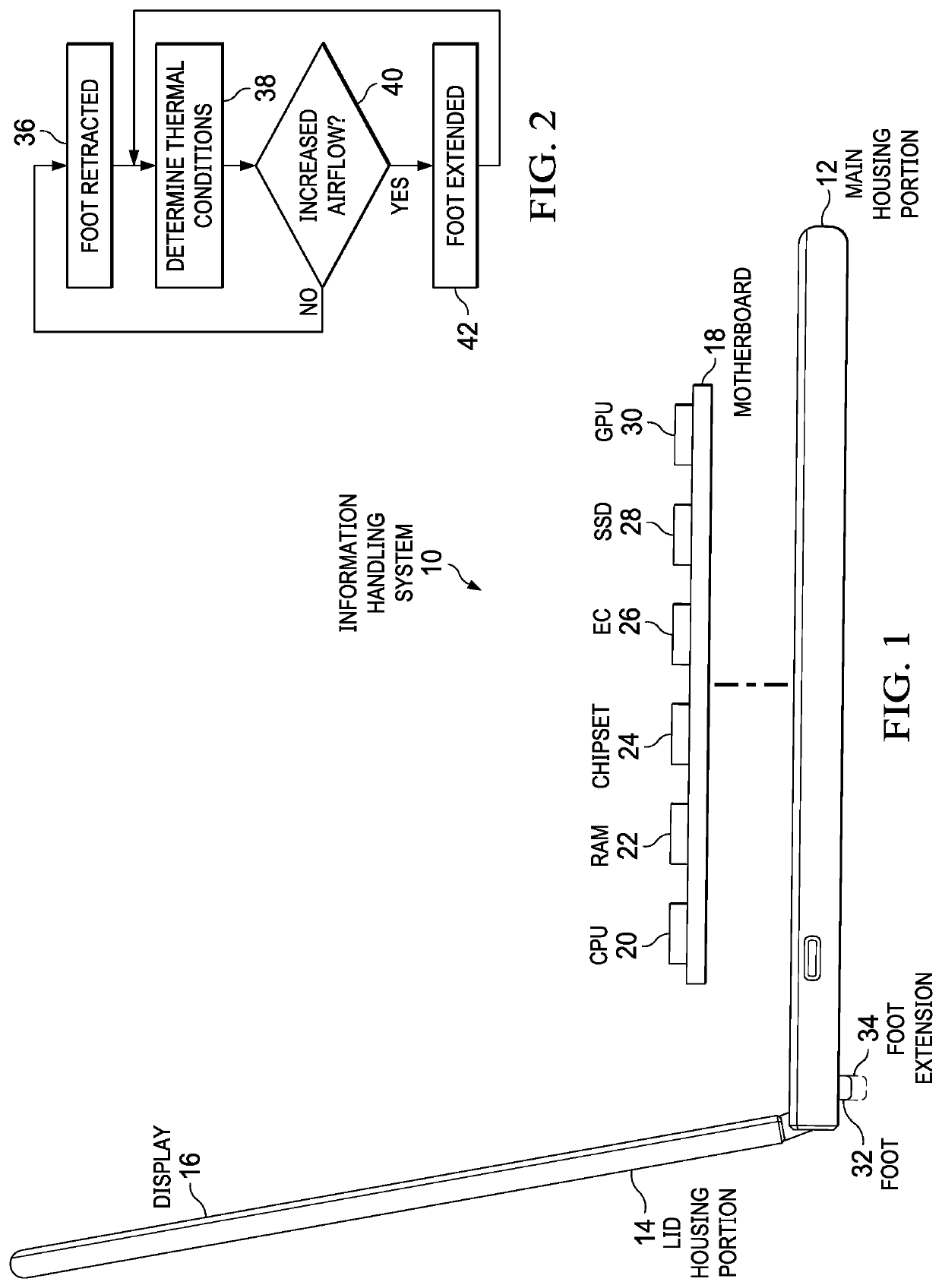
[0017]An information handling system dynamic foot at a housing bottom surface selectively extends and retracts to adapt airflow impedance to system thermal conditions. For purposes of this disclosure, an information handling system may include any instrumentality or aggregate of instrumentalities operable to compute, classify, process, transmit, receive, retrieve, originate, switch, store, display, manifest, detect, record, reproduce, handle, or utilize any form of information, intelligence, or data for business, scientific, control, or other purposes. For example, an information handling system may be a personal computer, a network storage device, or any other suitable device and may vary in size, shape, performance, functionality, and price. The information handling system may include random access memory (RAM), one or more processing resources such as a central processing unit (CPU) or hardware or software control logic, ROM, and / or other types of nonvolatile memory. Additional c...


PUM

PropertyMeasurementUnit
skin temperatureaaaaaaaaaa
currentaaaaaaaaaa
thermal stateaaaaaaaaaa

Abstract

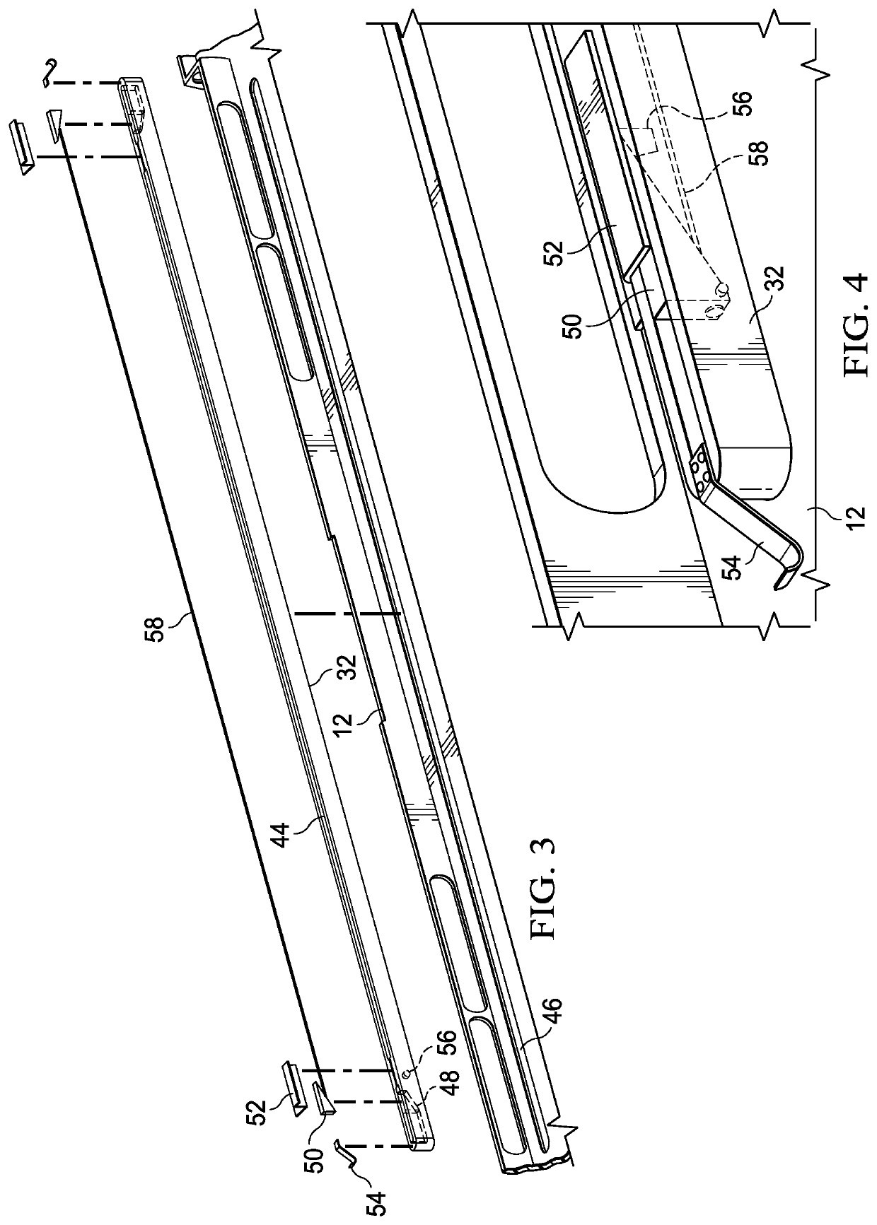
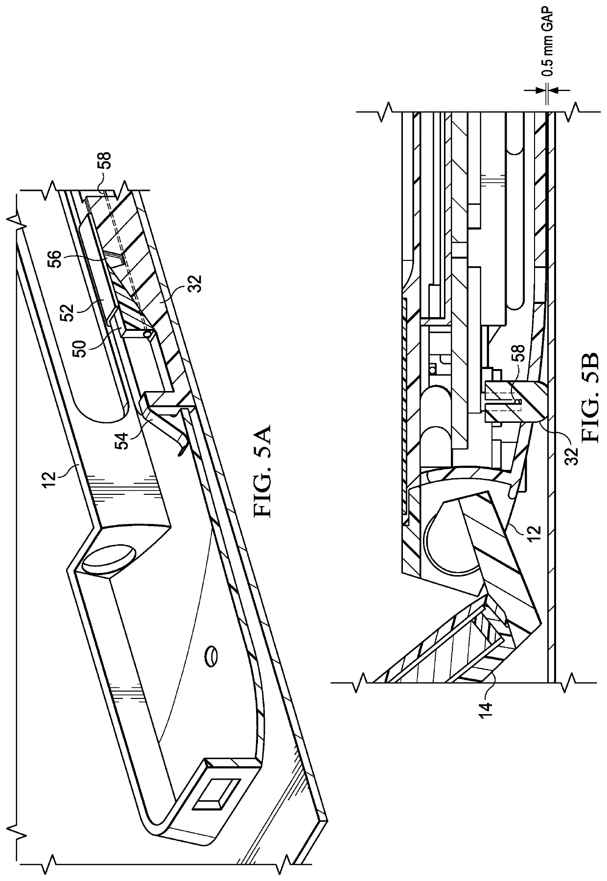
A portable information handling system has dynamic foot disposed at a bottom surface of a housing that extends and retracts to adjust cooling airflow impedance at vents disposed at the bottom surface. The dynamic foot includes an actuator in an internal cavity having opposing ramp structures interfaced by a nickel titanium wire that changes phase when heated to move the ramp structures. In the example embodiment, a push-push lock engages and disengages the ramp structures at each activation of the nickel titanium wire so that an embedded controller controls foot extension and retraction by applying current to the nickel titanium wire that heats the wire based upon detection of predetermined thermal conditions in the housing.

Description

BACKGROUND OF THE INVENTIONField of the Invention[0001]The present invention relates in general to the field of portable information handling systems, and more particularly to information handling system dynamic foot for adaptive thermal management.Description of the Related Art[0002]As the value and use of information continues to increase, individuals and businesses seek additional ways to process and store information. One option available to users is information handling systems. An information handling system generally processes, compiles, stores, and / or communicates information or data for business, personal, or other purposes thereby allowing users to take advantage of the value of the information. Because technology and information handling needs and requirements vary between different users or applications, information handling systems may also vary regarding what information is handled, how the information is handled, how much information is processed, stored, or communica...

Claims


Application Information

Patent Timeline
Patent Type & Authority Patents(United States)
IPC IPC(8): G01K1/00G05B15/02F16M11/10F16M13/00H05K5/02
CPCG01K1/00F16M11/10F16M13/00G05B15/02H05K5/0234F16M2200/08G06F1/203G06F1/206G06F1/166G06F1/1681
Inventor MCKITTRICK, ALLEN B.SHIH, POMINSHAW, TIMOTHY C.
Owner DELL PROD LP
Learn More