Optical assembly for scanning excitation radiation and/or manipulation radiation in a laser scanning microscope, and laser scanning microscope

a laser scanning microscope and optical assembly technology, applied in the field of optical arrangement of scanning excitation radiation and/or manipulation radiation in laser scanning microscopes, can solve the problems of complex and expensive microscope stands, difficult to implement further methods, and often have to carry out complex adjustments, etc., to achieve fast imaging and higher frequency

Active Publication Date: 2022-08-23
CARL ZEISS MICROSCOPY GMBH
View PDF13 Cites 0 Cited by
  • Summary
  • Abstract
  • Description
  • Claims
  • Application Information

AI Technical Summary

Benefits of technology

[0046]One major advantage of the present invention is that it becomes possible, in a laser scanning microscope, to carry out an imaging or an optical manipulation using quasi-static scanners, on the one hand, and a fast imaging by means of resonant scanners, on the other hand.
[0047]The term quasi-static scanner denotes a scanner which is not operated resonantly but rather, comparatively slowly, quasi-statically. Specifically, a drive curve can be impressed on a quasi-static scanner. Said drive curve can be linearized, for example, such that the same residence duration can be allocated to each pixel. Resonant scanners allow only sine-like movements, which, however, can have a significantly higher frequency. A resonant scanner or resonance scanner will operate in a mechanical resonance, in general comparatively much faster than a quasi-static scanner. Both the quasi-static scanner and the resonantly operated scanner can be realized by a galvanometric scanner, also referred to as galvoscanner, or a MEMS scanner.
[0048]In principle, acousto-optical devices, such as acousto-optical scanners, can also be used for the beam deflection devices, i.e. the scanners.
[0049]The invention enables switching to be effected very rapidly between a manipulation mode and an imaging. Very rapidly here means that the switching can be effected more rapidly than approximately 10 ms or more rapidly than 1 millisecond (ms).
[0050]This rapid switching is possible without the need to switch additional moving parts for beam path switching in the beam course. The instabilities and further

Problems solved by technology

A general technical problem here consists in generating, with the least possible expenditure in the most compact structural space possible and with the least possible transmission losses, a plurality of optical pupils which are in each case imaged onto one another.
This is disadvantageous since the microscope stand becomes complicated and expensive as a result.
Furthermore, under certain circumstances it is then not possible to implement further methods such as, for example, high-resolution microscopy on the same stand.
Moreover, complex adjustments often have to be carried out in order to bring the respective image fields to congruence with one another.
Known solutions for manipulation by means of only one scan objective are generally mechanical and thus often relatively slow.
In general it is virtually impossible for relatively large masses such as are constituted by mirrors, for example, to be switched faster than 10 ms.
However, here it is not possible to accommodate a z-scanning mirror in a fourth pupil.
The optical elements here have the degree of complexity of a scan objective that is complex and not very light-efficient.
However, individual axes cannot be switched in very rapidly because the masses to be moved are comparatively large.
However, there are no possibilities for switching between different scan modes.

Method used


Image

  • Optical assembly for scanning excitation radiation and/or manipulation radiation in a laser scanning microscope, and laser scanning microscope
  • Optical assembly for scanning excitation radiation and/or manipulation radiation in a laser scanning microscope, and laser scanning microscope
  • Optical assembly for scanning excitation radiation and/or manipulation radiation in a laser scanning microscope, and laser scanning microscope

Examples


Embodiment Construction

[0095]Identical and identically acting components are generally identified by the same reference signs in all of the figures.

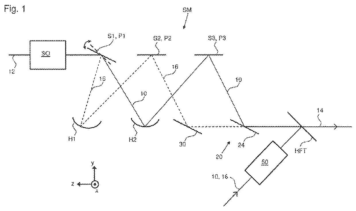
[0096]By way of example, the case in which a spatially targeted manipulation in a sample is performed by means of quasi-static scanners is considered below. Switching to an imaging is then intended to be effected very rapidly. What is taken as a basis here is the desire to record images of a specific size at a so-called video rate. In the case of laser scanning microscopes, this is possible using so-called resonance scanners, for example. For the following example from FIG. 1 it is furthermore assumed that both the optical manipulation and the excitation of fluorescence for the imaging are realized with a laser line at 488 nm, since this is a frequently occurring case of application.

[0097]The problem is solved by means of an optical arrangement SM according to the invention for scanning excitation radiation and / or manipulation radiation in a laser scanning mic...


PUM


Abstract

An optical assembly for scanning excitation radiation and / or manipulation radiation in a laser scanning microscope. The assembly an optical scanning unit as a first focusing device for providing a first pupil plane, a first beam deflecting device, which is made of a first scanner arranged in the first pupil plane, for scanning the excitation radiation and / or manipulation radiation in a first coordinate direction, and a second focusing device for generating a second pupil plane, which is optically conjugated to the first pupil plane. A second beam deflecting device is provided for deflecting the excitation radiation and / or manipulation radiation, said second deflecting device being arranged in the second pupil plane. A third focusing device is provided in order to generate a third pupil plane, optically conjugated to the first pupil plane. A third beam deflecting device is arranged in the third pupil plane in order to deflect the excitation radiation and / or manipulation radiation, and a variable beam deflecting means is provided in order to switch an optical beam path between a first beam path and a second beam path.

Description

RELATED APPLICATIONS[0001]The present application is a U.S. National Stage application of International PCT Application No. PCT / EP2018 / 072821 filed on Aug. 23, 2018 which claims priority benefit of German Application No. DE 10 2017 119 480.0 filed on Aug. 25, 2017, the contents of each are incorporated by reference in their entirety.FIELD OF THE INVENTION[0002]The present invention relates, in a first aspect, to an optical arrangement for scanning excitation radiation and / or manipulation radiation in a laser scanning microscope according to the preamble of the first claim directed to an optical arrangement. In a further aspect, the invention relates to a laser scanning microscope according to the preamble of the first claim directed to a laser scanning microscope.BACKGROUND OF THE INVENTION[0003]A generic optical arrangement for scanning excitation radiation and / or manipulation radiation in a laser scanning microscope, and specifically in a laser scanning fluorescence microscope, is...

Claims


Application Information

Patent Timeline
Patent Type & Authority Patents(United States)
IPC IPC(8): G02B21/00G02B27/28G02B3/06
CPCG02B21/0048G02B21/0032G02B21/0076G02B27/283G02B3/06G02B21/24
Inventor ANHUT, TIEMOWALD, MATTHIASSCHWEDT, DANIELBÖHME, BEATE
Owner CARL ZEISS MICROSCOPY GMBH
Why Eureka
Try Eureka