
Ultrasound based tracking

a tracking system and ultrasound technology, applied in the field of ultrasound-based tracking systems, can solve the problems of difficult visualization of medical devices such as needles, catheters and interventional tools in ultrasound images, and the need to calibrate the coordinate system of the tracking system to the field of view of the ultrasound probe, so as to achieve the effect of avoiding the problem of poor visibility

Active Publication Date: 2022-08-16
KONINKLJIJKE PHILIPS NV
View PDF21 Cites 0 Cited by
  • Summary
  • Abstract
  • Description
  • Claims
  • Application Information

AI Technical Summary

Benefits of technology

This patent describes a way to attach a frame to an ultrasound imaging probe to track the position of a medical device attached to it. The frame has markers that can be seen on the ultrasound image, and by attaching a reference volume to the frame and then attaching the frame to the ultrasound probe, the system can calibrate its tracking to the ultrasound field of view. This way, the medical device can be easily tracked during ultrasound procedures.

Problems solved by technology

Medical devices such as needles, catheters and interventional tools are often difficult to visualize in an ultrasound image due to the specular nature of their reflectivity, particularly at unfavorable incidence angles.
A drawback of known localization systems in which tracking is provided by different transducers to those of the ultrasound probe, is the need to calibrate the coordinate system of the tracking system to the field of view of the ultrasound probe.

Method used


Image

  • Ultrasound based tracking
  • Ultrasound based tracking
  • Ultrasound based tracking

Examples


Embodiment Construction

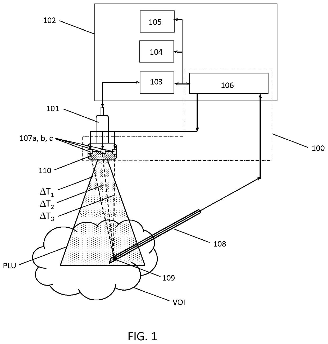
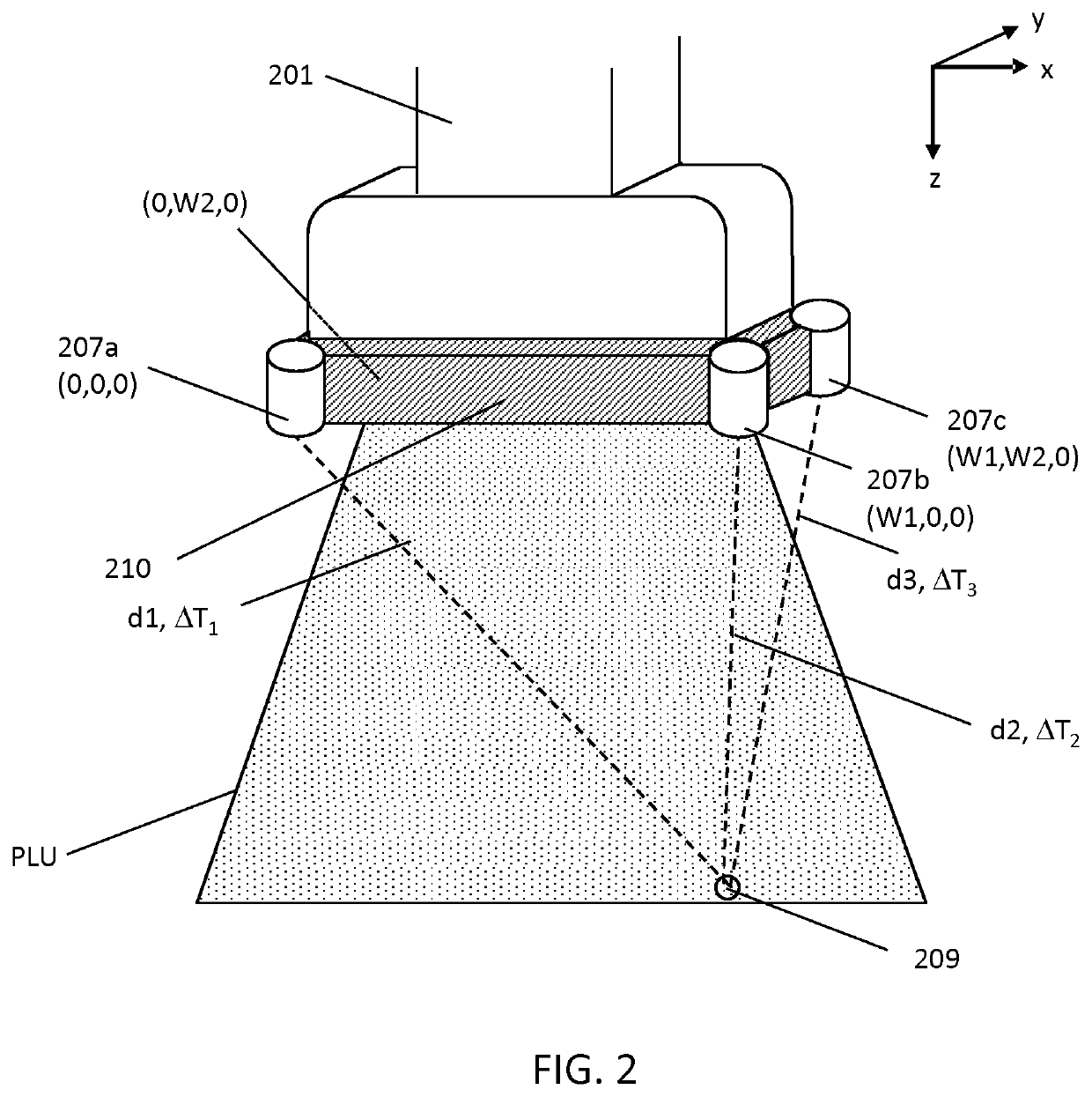
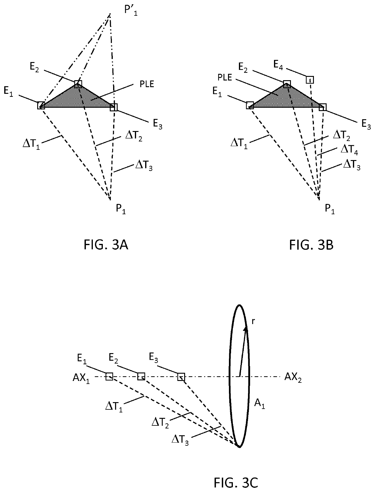
[0018]In order to illustrate the principles of the present invention, various systems are described in which the tracking of a medical device, exemplified by a needle, is provided by a position triangulation unit and three ultrasound emitters that are attachable to a 2D ultrasound imaging probe. It is however to be appreciated that the invention also finds application in the tracking of other medical devices such as a catheter, a guidewire, a probe, an endoscope, an electrode, a robot, a filter device, a balloon device, a stent, a mitral clip, a left atrial appendage closure device, an aortic valve, a pacemaker, an intravenous line, a drainage line, a surgical tool such as a tissue sealing device or a tissue cutting device. It is also to be appreciated that the invention finds application with other types of ultrasound imaging probes such as a 3D imaging probe, a transesophageal probe (TEE), transthoracic probe (TTE), transnasal probe (TNE), intracardiac probe (ICE), intravascular p...


PUM


Abstract

The present invention relates to an ultrasound-based system for localizing a medical device within the field of view of an ultrasound imaging probe. A localization system is provided that includes at least three ultrasound emitters that are arranged on a frame; and a position triangulation unit. The frame is adapted for attachment to an ultrasound imaging probe. The position triangulation unit determines a spatial position of the ultrasound detector relative to the at least three ultrasound emitters based on signals received from an ultrasound detector that is attached to the medical device. The frame includes a detachable reference volume comprising a background volume and an inclusion or void. When the detachable reference volume is attached to the frame and the frame is attached to the ultrasound imaging probe the inclusion or void provides a corresponding image feature within the field of view of the ultrasound imaging probe for use in calibrating the field of view of the ultrasound imaging probe with the coordinate system of the localization system.

Description

CROSS-REFERENCE TO PRIOR APPLICATIONS[0001]This application is the U.S. National Phase application under 35 U.S.C. § 371 of International Application No. PCT / EP2016 / 080708, filed on Dec. 13, 2016, which claims the benefit of European Patent Application No. 15201890.9, filed on Dec. 22, 2015. These applications are hereby incorporated by reference herein.FIELD OF THE INVENTION[0002]The present invention relates to an ultrasound-based system for localizing a medical device within the field of view of an ultrasound imaging probe.BACKGROUND OF THE INVENTION[0003]Medical devices such as needles, catheters and interventional tools are often difficult to visualize in an ultrasound image due to the specular nature of their reflectivity, particularly at unfavorable incidence angles.[0004]In one solution to this problem, patent application WO2015 / 101949 discloses a tool navigation system employing an ultrasound probe, an ultrasound scanner, and an interventional tool. The ultrasound scanner g...

Claims


Application Information

Patent Timeline
Patent Type & Authority Patents(United States)
IPC IPC(8): A61B34/20A61B8/00G01S5/30A61B8/08A61B90/00A61B8/12G01S17/48
CPCA61B8/4245A61B8/0841A61B8/4254A61B8/4444A61B34/20G01S5/30A61B8/12A61B8/587A61B2034/2063A61B2090/378A61B2090/3786G01S17/48
Inventor VAN DE PAS, STEFANSTAPERT, HENDRIK ROELOF
Owner KONINKLJIJKE PHILIPS NV
Learn More