Eureka AIR delivers breakthrough ideas for toughest innovation challenges, trusted by R&D personnel around the world.

Zero discharge water treatment apparatus and method

a technology of water treatment apparatus and equipment, applied in the direction of water treatment multi-stage treatment, water/sewage multi-stage treatment, separation process, etc., can solve the problems of increasing the importance of waste water treatment plants, and increasing the burden on municipal services

Active Publication Date: 2022-07-19
ZERO DISCHARGE LLC
View PDF38 Cites 1 Cited by
  • Summary
  • Abstract
  • Description
  • Claims
  • Application Information

AI Technical Summary

Benefits of technology

[0006]The intent of this disclosure is to provide an apparatus and means to completely purify and reuse water brought into a building / facility in a cycle designed to minimize the wasting of water, to eliminate the unnecessary dumping of contaminated water back into an aquifer surrounding the building / facility and to thereby eliminate heretofore existing contaminants. The disclosure also provides for the use of alternate energy methods and sources to enhance the environmentally-conscious water treatment and water conservation processes and to alleviate and make as independent as possible, a building / facility from the infrastructure of a municipality. Other purposes of this disclosure include the elimination or reduction of carbon emissions created in water treatment processes, the prevention of nitrate / nitrite deposits into groundwater and the total destruction of all organic contaminants (including polyfluoroalkyl substances (PFASs)) and inorganic pathogens existent in original water supplies.
[0010]In a further aspect of the disclosure, the evaporator unit(s) can be either vacuum or atmospheric units. Vacuum units reduce the pressure in the unit which facilitates evaporation at a much lower temperature and lower the cost per gallon of wastewater evaporated. An atmospheric based evaporator system does not alter the pressure within the unit and requires larger amounts of energy than the vacuum-based units to evaporate water.
[0011]In yet another aspect of the disclosure, a sonolysis unit is used to break up harmful chemical compounds found in waste water. The sonolysis unit uses a plurality of sound emitting devices to create cavitation bubbles that significantly increase the temperature and pressure in the bubbles to break down chemical components. Use of a sonolysis unit eliminates harmful chemicals before the treated fluids are further processed by the evaporator unit(s).
[0012]In a still further aspect of the disclosure, a continuous-cycle autoclave is positioned between the UV unit and the evaporator unit(s) to apply high heat and pressure to break down and eliminate harmful chemical compounds in waste water. The autoclave uses steam created by the evaporator in a feed-back loop to increase the pressure and temperature in the autoclave. This leads to the destruction of the unwanted chemical compounds and releases treated water to the evaporator at an elevated temperature that reduces the energy requirements to further process the water introduced into the evaporator via pure evaporation and / or distillation. These and other aspects of the disclosure will become apparent from a review of the appended drawings and a reading of the following detailed description of the disclosure.

Problems solved by technology

Such large-scale residential real estate developments place a significant burden on municipal services.
In similar fashion, commercial developments such as office buildings and medical facilities also place a significant burden on municipal services, especially water and sewer services.
The impact of new housing or commercial real estate developments on waste water treatment plants is becoming ever more significant as any such plant has capacity limits.
For this reason, among many urban planning issues, limitations have to be placed on the number of building permits issued by a municipality.
If septic systems are needed, the issue is much more pronounced.
Either way, wastewater produced by a housing or other building project adds either to the municipal burden or the environmental burden.

Method used


Image

  • Zero discharge water treatment apparatus and method
  • Zero discharge water treatment apparatus and method
  • Zero discharge water treatment apparatus and method

Examples


Embodiment Construction

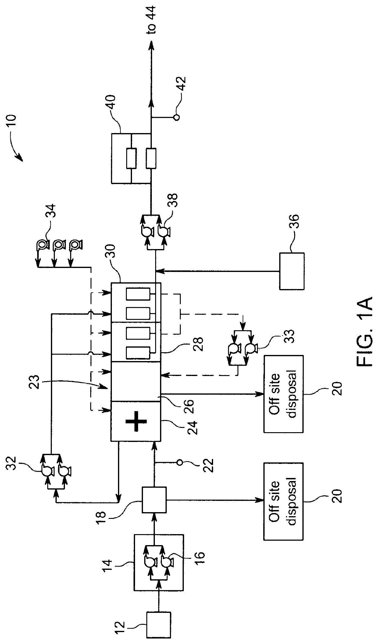
[0031]Referring to FIG. 1A, in one aspect of the disclosure, a wastewater treatment system shown generally as 10 includes a series of components to separate and reduce raw sewage into disposable solids and reusable liquids brought to the system by a building plumbing system. The raw sewage is first deposited into one or more pretreatment tanks 12 that function as septic tanks to separate grease, grit and primary solids from the liquid component of the wastewater. The solids component is shipped offsite according to means used with conventional septic systems as is known in the art. The clarified liquid component is transferred via pipe system to one or more flow equalization tanks 14 that each include one or more influent pumps 16. Pumps 16 are used to force the clarified liquid through a fine screen 18 before further transfer in system 10. Fine screen 18 has a mesh selected for the particular solids being filtered out as is well known in the art.

[0032]Any particulate matter filtere...


PUM

PropertyMeasurementUnit
temperatureaaaaaaaaaa
pressureaaaaaaaaaa

Abstract

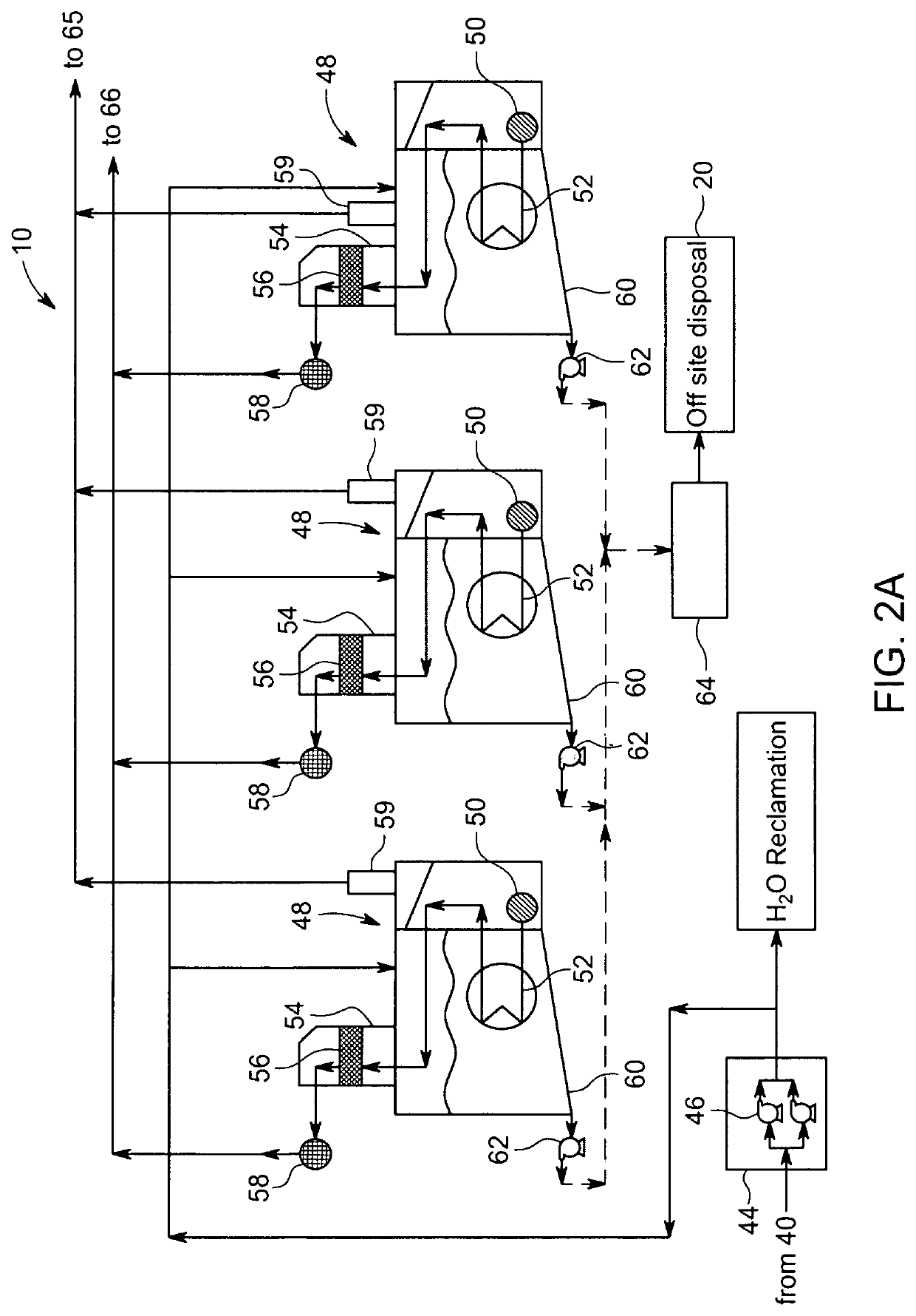
A wastewater management system includes a series of holding tanks in combination with a membrane bioreactor treatment subsystem connected to one or more autoclaves and / or sonolysis units and thermal evaporators to treat liquid discharge from the system. A condenser connected to the thermal evaporator(s) condenses water vapor created by the thermal evaporator(s) into its liquid state for delivery to, and assimilation by, plants in a dedicated greenhouse or hydroponic system or for reuse in a building. CO2 and water vapor produced by combustion of a thermal evaporator fuel source is sent through the condenser to add to the liquid water recovery. The CO2 is flowed into the greenhouse(s) for carbon fixation by plants. A CO2 monitoring system ensures the concentration of CO2 in the greenhouse is maintained at an acceptable level for humans. Ozonation, UV and / or chloride treatments may be used as optional water purification treatments in the system.

Description

CROSS-REFERENCE TO RELATED APPLICATIONS[0001]This regular utility application claims the benefit of U.S. Provisional Application Ser. No. 62 / 839,901, filed Apr. 29, 2019, the contents of which are incorporated herein by reference.FIELD OF THE DISCLOSURE[0002]This disclosure relates to apparatus and methods to treat wastewater in large multi-unit housing buildings and large commercial buildings. More particularly, the disclosure relates to apparatus and methods to achieve zero wastewater discharge and reduce emission discharge from buildings having multiple bathrooms and water usage and disposal limitations. The disclosure also relates to apparatus and methods to treat contaminated wastewater and to reduce overall water usage for a particular building complex.BACKGROUND OF THE DISCLOSURE[0003]With ever increasing housing costs, particularly those associated with single family homes, more and more developments involve condominium and apartment complexes to provide more affordable hous...

Claims


Application Information

Patent Timeline
Patent Type & Authority Patents(United States)
IPC IPC(8): C02F3/12C02F1/44C02F1/04C02F1/72C02F9/00C02F1/00
CPCC02F3/1268C02F1/001C02F1/048C02F1/447C02F1/72C02F9/00C02F2301/08C02F1/042B01D5/006C02F1/32C02F1/36C02F1/76C02F1/78C02F2001/007C02F2303/24C02F1/302C02F1/16Y02A20/00C02F1/325Y02W10/10Y02W10/37
Inventor CALHOUN, DAVID D.LORUSSO, MARK D.ROSE, JR., R. EDWARD
Owner ZERO DISCHARGE LLC
Why Eureka
Eureka Blog
Learn More