
Statically balanced crank-operated packer mechanism for an agricultural baler

a technology of agricultural balers and cranks, which is applied in the field of crank-operated packer mechanisms, can solve the problems of insufficient robustness and/or difficult assembly and disassembly, premature wear and possible failure of shafts, and reduce the cost of crank pins and/or crank arms. , the effect of reducing the cost of pins

Active Publication Date: 2022-05-24
BLUE LEAF I P INC
View PDF17 Cites 0 Cited by
  • Summary
  • Abstract
  • Description
  • Claims
  • Application Information

AI Technical Summary

Benefits of technology

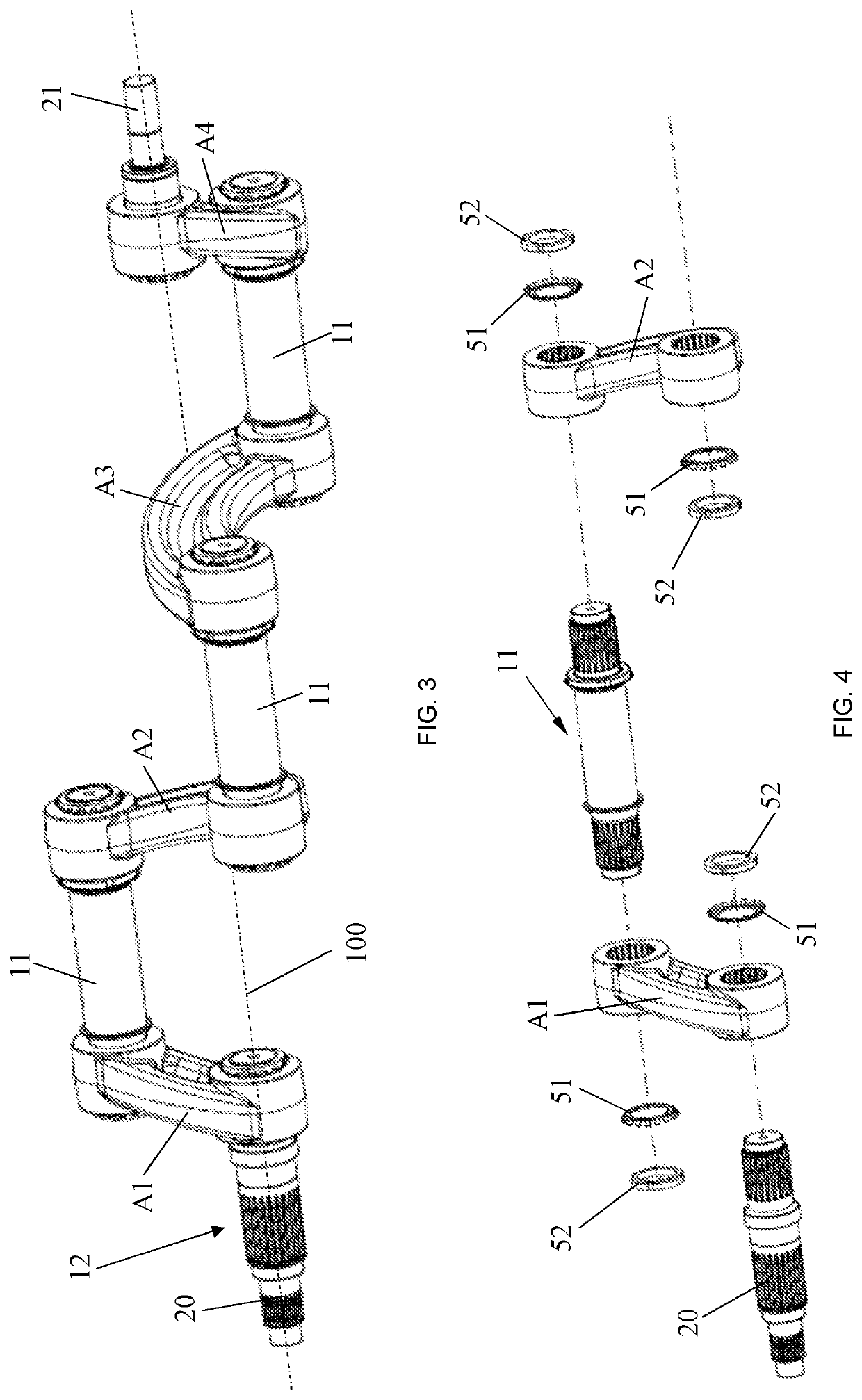
[0009]The tapered spline features realize a strong connection while allowing the separate optimization of the crank pins and the crank arms in terms of their design and material choice. For example, the crank pins may be produced from a steel type having a high toughness and flexibility, while the crank arms may be produced from cast iron.
[0010]By choosing a number of tapered spline features at each outer end of the crank pins that is an integer multiple of the number of crank pins, the pins can be produced identical to each other, which decreases the cost of the pins and makes replacement of the crank pins and / or crank arms more straightforward.

Problems solved by technology

The crank shaft-operated packer mechanisms often use welded crank shafts which however exhibit weak spots due to the welding process.
This makes these shafts vulnerable to premature failure as a consequence of the high torsion forces occurring during operation.
Assembled crank shafts for packer mechanisms have been documented but these are often insufficiently robust and / or difficult to assemble and disassemble.
Also, present-day packer crank shafts having more than 2 eccentric crank pins are often statically unstable, leading to premature wear and possible failure of the shaft.

Method used


Image

  • Statically balanced crank-operated packer mechanism for an agricultural baler
  • Statically balanced crank-operated packer mechanism for an agricultural baler
  • Statically balanced crank-operated packer mechanism for an agricultural baler

Examples


Embodiment Construction

[0033]Preferred embodiments will now be described with reference to the drawings. The detailed description is not limiting the scope of the invention, which is defined only by the appended claims.

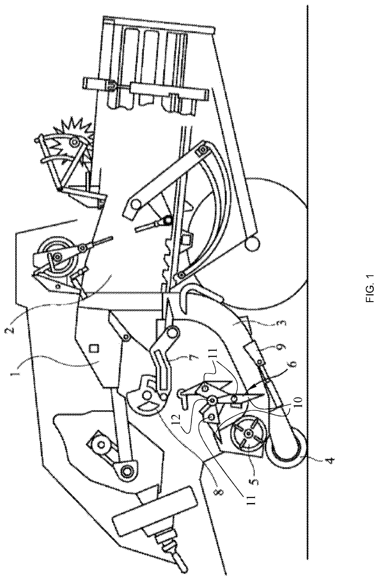
[0034]FIG. 1 illustrates an example of a square baler presently known in the art. The following components are indicated: the plunger 1, the baling chamber 2, the pre-compression chamber 3, a pick-up mechanism 4 and a guide roll 5 configured to transport crops towards a packer mechanism 6 for supplying crops to the pre-compression chamber 3, and a stuffer fork 7 configured to push a slice of crops that has gathered in the pre-compression chamber 3, upwards into the baling chamber 2. The stuffer fork 7 is actuated by a rotatable drive means 8, configured to drive the fork 7 only when the pre-compression chamber is full (as detected by a detector 9), and when the plunger 1 is in the retracted position.

[0035]The packer mechanism 6 comprises packer teeth 10 which are rotatably mounted on the ec...


PUM


Abstract

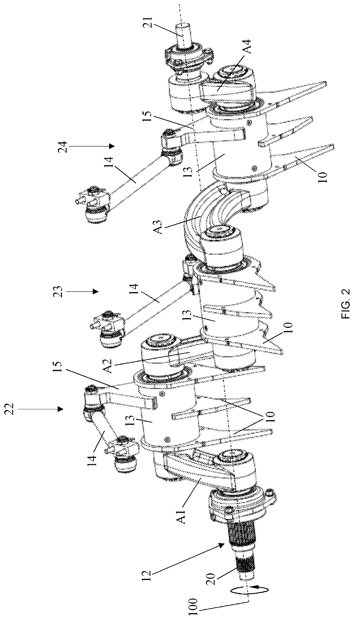
A crank-operated packer mechanism includes a crank shaft including crank pins and crank arms. At least some of the crank arms are shaped in a way that deviates from a straight shape to such an extent that the crank shaft is statically balanced. The arms may, for example, be curved or hook-shaped. The crank shaft further includes crank pins and crank arms assembled by a tapered spline connection. The connection includes tapered spline features on outer ends of the crank pins and in openings provided at outer ends of the crank arms, which interlock when the crank pins are inserted in the openings.

Description

FIELD OF THE INVENTION[0001]The present invention is related to agricultural balers, designed for processing crops or crop residue into dense bales maintained by wires, straps or other binding materials. The invention is in particular related to a crank-operated packer mechanism applicable primarily in a so-called ‘square’ baler, i.e. a baler for processing square or rectangular bales, even though the mechanism of the invention is applicable to any type of baler requiring the packing of crop material into a pre-compression chamber.STATE OF THE ART[0002]Agricultural balers can be either stationary machines to which crops are loaded, or self-propelled or towable machines which pick up crops from the field and automatically process the crops into bales. In a square baler, a packer mechanism moves the received or collected crops into a curved or slanted pre-compression chamber from which the crops are then moved into the baling chamber where they are compressed by a reciprocating plunge...

Claims


Application Information

Patent Timeline
Patent Type & Authority Patents(United States)
IPC IPC(8): A01F15/10
CPCA01F15/101A01F15/106A01F2015/102A01D89/008
Inventor VAN HULLEBUSCH, BART G. L.GRYSON, RUBEN
Owner BLUE LEAF I P INC
Learn More